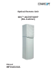
Optical Remote Unit ION™-M17HP/19HP (ML-Cabinet) Manual MF0143AXA
Manual for ION™-M17HP/19HP (ML-cab) © Copyright 2011 CommScope, Inc. All rights reserved. Andrew Solutions is a trademark of CommScope, Inc. All information contained in this manual has been revised thoroughly. Yet Andrew Solutions accepts no liability for any omissions or faults. Andrew Solutions reserves the right to change all hard- and software characteristics without notice.
TABLE OF CONTENTS 1. GENERAL 6 1.1. USED ABBREVIATIONS 6 1.2. HEALTH AND SAFETY WARNINGS 7 1.3. ABOUT ANDREW SOLUTIONS 9 1.4. INTERNATIONAL CONTACT ADDRESSES FOR CUSTOMER SUPPORT 10 2. FUNCTIONAL DESCRIPTION 12 2.1. PURPOSE 12 2.2. THE ION-M17HP/19HP (INTELLIGENT OPTICAL NETWORK; MMR) 12 3. COMMISSIONING 15 3.1. 3.1.1. 3.1.2. 3.1.3. MECHANICAL INSTALLATION General Wall Mounting of RU Pole Mounting of RU 15 15 17 18 3.2. 3.2.1. 3.2.2. 3.2.3.
Manual for ION™-M17HP/19HP (ML-cab) 4.6. TROUBLESHOOTING 38 5. MAINTENANCE 39 5.1. GENERAL 39 5.2. REPLACING THE FAN UNIT 40 5.3. CLEANING THE HEAT SINK 41 6. APPENDIX 42 6.1. ILLUSTRATIONS 42 6.2. 6.2.1. 6.2.2. 6.2.3. SPECIFICATIONS Electrical Specifications Mechanical Specifications Environmental and Safety Specifications 43 43 43 43 6.3. SPARE PARTS 44 7. INDEX Page 4 45 Manual ION-M17HP-19HP MF0143AXA.
FIGURES AND TABLES figure 3-1 Mounting bracket installation .................................................................... 17 figure 3-2 RU wall mounting ..................................................................................... 17 figure 3-3 Pole-mounting kit, view from different sides ............................................. 18 figure 3-4 Pole-mounting, ML-cabinet, assembly drawing ........................................ 19 figure 3-5 Pole mounting of RU, finished ..................
Manual for ION™-M17HP/19HP (ML-cab) 1. GENERAL 1.1.
SCL SDA SISO SPD SRMU TCH TDD TDMA TX UL UMR UMTS UPS VSWR WDM WiMAX Serial Clock Serial Data Single Input Single Output Switching Point Detector Subrack Master Unit = OTRx (Optical Transceiver) Traffic Channel Time-Division Duplex Time Division Multiple Access Transmitter Uplink Universal Measurement Receiver Universal Mobile Telecommunication System Uninterruptible Power Supply Voltage Standing Wave Ratio Wavelength Division Multiplex Worldwide Interoperability for Microwave Access 1.2.
7. Note for a Class A digital device or peripheral: This equipment has been tested and found to comply with the limits for a Class A digital device, pursuant to part 15 of the FCC Rules. These limits are designed to provide reasonable protection against harmful interference when the equipment is operated in a commercial environment.
1.3. ABOUT ANDREW SOLUTIONS Andrew Wireless Systems GmbH based in Buchdorf/ Germany, is a leading manufacturer of coverage equipment for mobile radio networks, specializing in high performance, RF and optical repeaters. Our optical distributed networks and RF repeater systems provide coverage for every application: outdoor use, indoor installations, tunnels, subways and many more.
1.4. INTERNATIONAL CONTACT ADDRESSES FOR CUSTOMER SUPPORT Americas: Canada United States Andrew Solutions Canada Andrew Solutions, Andrew LLC, A CommScope Company Mail 620 North Greenfield Parkway Garner, NC 27529 U.S.A. Mail 620 North Greenfield Parkway Garner, NC 27529 U.S.A. Phone +1-905-878-3457 (Office) +1 416-721-5058 (Mobile) Phone +1-888-297-6433 Fax +1-905-878-3297 Fax +1-919-329-8950 E-mail Peter.Masih@andrew.com WIsupport.us@andrew.com E-mail WIsupport.us@andrew.
Europe: United Kingdom France Andrew Solutions UK Ltd Andrew Solutions France Mail Unit 15, Ilex House Mulberry Business Park Fishponds Road Wokingham Berkshire RG41 2GY England Mail 28, Rue Fresnel Z.A Pariwest BP 182 78313 Coignières Cedex France Phone +44-1189-366-792 Phone +33 1 30 05 45 50 Fax +44-1189-366-773 Fax +33 1 34 61 13 74 E-mail WIsupport.uk@andrew.com E-mail WIsupport@andrew.
2. FUNCTIONAL DESCRIPTION 2.1. PURPOSE Cellular telephone systems transmit signals in two directions between base transceiver station (BTS) and mobile stations (MS) within the signal coverage area. If weak signal transmissions occur within the coverage area because of indoor applications, topological conditions or distance from the transmitter, extension of the transmission range can be achieved by means of an optical distribution system.
The ION-M17HP/19HP is available in a multi-band configuration supporting 1900 MHz and 1700/2100 MHz in parallel. It has been specifically tested and optimized for GSM, EDGE, HSPA+, OFDM, EV-DO and WCDMA. Furthermore it is provisioned for future improvements to the modulation and frequency bands. The ION is easily set-up and supervised via a graphical user interface (GUI). Remote Units can be commissioned through the use of built-in test equipment.
For your notes: Page 14 Manual ION-M17HP-19HP MF0143AXA.
3. COMMISSIONING 3.1. MECHANICAL INSTALLATION 3.1.1. General Read the health and safety warnings in section 1.2 Health and Safety Warnings. 1. Do not install the unit in a way or at a place where the specifications outlined in the Environmental and Safety Specifications leaflet of the supplier are not met. 2. Use the mounting hardware delivered by the manufacturer only. If different mounting hardware is used, the specifications for stationary use of the Remote Unit must not be exceeded.
7. A spacing of 40 mm (1.58 inch) around the unit is required. 8. To ensure sufficient airflow when mounting the unit in enclosed spaces, two lid openings (one for the air inlet and the other for the air outlet) have to be provided. Do not block these air inlets and outlets when mounting the Remote Unit. The size of each opening must equal at least 17 x 17 cm (290 cm2). Make sure, too, there is no thermal short circuit between the air inlet and air outlet.
3.1.2. Wall Mounting of RU Check the suitability of the wall-mounting kit and the wall. Mark the position of the drilling holes (for measurements and a more detailed description refer to the wall mounting plan that is part of the delivery). Drill four holes at the marked positions and insert dowels*. Screw the mounting brackets to the wall / dowels using the four dowel screws as illustrated in figure 3-1 Mounting bracket installation.
3.1.3. Pole Mounting of RU The standard mounting hardware also includes all parts required for pole mounting: Plain washers for M8.0 M8.0x25 hexagon head screws Split-lock washers Screw bands (stainless steel) Wall/ Pole mounting brackets figure 3-3 Pole-mounting kit, view from different sides Note: The screw bands illustrated above are equipped with quick-release snaplock clamps which must be disengaged to be applied.
Ensure that there is free access to the electrical connections as well as to the cabinet. The approved bending radius of the connected cables must not be exceeded. Wall-/ Pole mounting bracket Wall-/ Pole mounting bracket Screw bands Screw bands Split-lock washer for M8.0 G3219M001 M8.0x25 hexagon head-screw Note: Plain washer for M8.0 All unmarked screw joints illustrated above have nominal tightening torque values according to QA 7.5.1.090/F1011P0.
3.2. ELECTRICAL INSTALLATION 3.2.1. General Read the health and safety warnings in section 1.2 Health and Safety Warnings. 1. This unit contains dangerous voltages. Loss of life, severe personal injury or property damage can be the result if the instructions contained in this manual are not followed. 2. Ground the unit before connecting power supply. A grounding bolt is provided on the cabinet to connect the ground-bonding cable. 3.
12. The unit complies with the surge requirement according to EN 61000-4-5 (fine protection); however, it is recommended to install an additional medium (via local supply connection) and/or coarse protection (external surge protection), depending on the individual application, in order to avoid damage caused by overcurrent. 13. Observe the labels on the front panels before connecting or disconnecting any cables. 3.2.2.
Control Connector (RS485 / RS232) This 8-pin male connector (type: Binder Series 712) primarily supports control of the Extension Unit via RS485 bus. PIN 1 2 3 4 5 6 7 8 figure 3-7 RS485 connector Assignment not connected RS232 Rx RS232 Tx not connected GND (RS232) RS485 R+/D+ RS485 GND RS485 R-/D- table 3-2 RS485 connector, pin assignment 3.2.3. Grounding Grounding must be carried out. Connect an earth-bonding cable to the grounding connection provided at the outside of the Remote Unit (see section 3.2.
3.3. CONNECTION OF THE ANTENNA CABLES The Remote Unit has 7/16-type antenna connectors. For its location please refer to section 3.2.2 Connections. For mounting the cable connectors, it is recommended to refer to the corresponding documentation of the connector manufacturer. The bending radius of the antenna cables must remain within the given specifications.
For the AC power supply connection, a minimum cross section of 1.5 mm2 is required. Each wire must observe the applicable national regulations regarding loop impedance, voltage drop, and methods of installation. Make sure to connect the correct voltage to the unit. Note: * Do not connect or disconnect the power cord at the power supply connector while power is on. Turn off mains power * before connecting the power cord at the Remote Unit, then, engage mains power again.
Fiber-System Installation: Fiber-cable connectors have to be of the same type (E2000APC8°) as the connectors used for the unit. The fiber-optic cables are connected to the optical transceiver. Angled connectors are not compatible with straight optical connectors; non-compatibility of connectors will result in permanent damage to both connectors. Before connecting the fiber cables, follow the procedure below to ensure optimized performance.
Cleaning Procedure for Fiber-Optical Components: Any contamination in the fiber connection results in additional optical transmission loss which could cause whole system failure. It is thus recommended that every fiber connector be inspected and cleaned prior to mating. The goal is to eliminate any dust or contamination and to provide a clean environment for the fiber-optic connection. When you clean fiber components, always complete the following steps carefully: 1.
3.5.1. Protective Plug Connection: A protective plug is provided for the connection of the fiber-optic cables. figure 3-11 Protective-plug assembly Note: Only high-quality connectors must be used for this type of plug. Qualified brands are Diamond or Huber & Suhner.
For plug assembly, observe the following instruction: 1. Pass one or two contacts through the backshell and the clamp ring. 2. Place the contact(s) on the lower insulation body by pushing the groove of the contact into the cavity. If there is only one contact, cavity A must be used. * 3. Then, mount the upper insulation body on the lower insulation body. ** Upper insulation body Cavity B Cavity A 4. Bring the insulator into the plug.
7. Bring the plastic ring over the cable(s), push it into the backshell and compress the seals and plastic ring by screwing the clamp ring tight (no gap) using a spanner with opening 20. *** Screw tight until gap is closed 8. Connect the plug to the optical-fiber 9. To lock the connector, push the black connector of the Remote Unit, again locking ring forward.**** by fitting a stamp on the plug into the groove of the connector.
Protective plug Fiber cable Ring 3/4 Reducer Screw the reducer to the protective plug backshell without any gap! Coupling Place the appropriate seal parts (with) one groove for one contact or two grooves for two contacts) over the cable(s) and push them into the backshell! Protective tube Push the fiber-optic cable carefully through the tube until it comes out at the other end. G1055M0 figure 3-12 Tube-kit installation Page 30 Manual ION-M17HP-19HP MF0143AXA.
3.6. COMMISSIONING Read the health and safety warnings in section 1.2 Health and Safety Warnings. Keep these guidelines in mind before continuing to the instructions for commissioning: Do not operate the Remote Unit without terminating the antenna connectors. The antenna connectors may be terminated by connecting them to their respective antennas or to a dummy load.
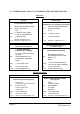
Commissioning an ION-M Remote Unit Manual for Remote Unit Philips screwdriver Mounting kit Spanner, size 13 mm Drilling machine Dowels Screw driver Screw driver Spanner, size 13 mm Start Preperation Unpack RU, RU accessories and mounting kit. Mechanical installation Fasten wall or pole mounting kit to wall or pole. Mechanical installation Mount RU to mounting kit, ensure suffient air flow and avoid thermal short circuits.
No LED on? Check power switch inside RU (RUs with door). Check mains cabling. Check mains power. Yes Red LED status Internal Error Change power supply (RUs with a door). Reduce environmental temperature. Eliminate thermal short circuit. Disconnect and connect mains. Fans should run. If not, replace the fans at RU. MU: Change amplifier setting at MU controller Orange Yellow LED status Red Green Spare RU available? External error Close the door (RUs with a door).
For your notes: Page 34 Manual ION-M17HP-19HP MF0143AXA.
4. ALARMS 4.1. BITe AND ALARMS The Built-In Test (BITe) concept comprises the monitoring of the power supplies, the power amplifiers and the optical interface. All alarms occurring can be checked via software at the Master Unit. 4.2. HANDLING OF ALARMS A message is transmitted to the Master Unit when the software acknowledges a valid alarm. A new alarm message will not be repeated if the reason for the alarm is cleared or if the alarm continues.
4.4. STATUS LED ALARMS For local supervision, a status LED on the connector flange of the Remote Unit gives an indication of possible reasons for alarms. This table shows possible on-site measures that could be checked before referring to the Master Unit alarm list. Status LED Indication Green Orange Red Status LED off Alarms Possible on-site measures No alarm Status ok Door alarm Close the door (RUs with door). Alarms not directly related to RU: External alarms Check externally connected devices.
4.5. EXTERNAL ALARM INPUTS AND OUTPUTS G1038Z0 figure 4-1 Flange connector, 5 poles G1038Z0 figure 4-2 Flange connector, 7 poles The alarm outputs (open collector output 5 V / 1 mA) are normally low. In case of an alarm they are high active (5 V). They can be used to monitor alarms with an external alarm indicator. The +28 V pin (for its location see figure 4-2 Flange connector, 7 poles) is protected by a 500 mA thermoswitch.
With the external alarm inputs it is possible to monitor the status of connected devices, e.g. a UPS, via software. All alarm inputs are normally high (5 V) without connection. The polarity (high/ low) can be set via the software at the Master Unit (for details please see according software manual). The device to be monitored must be connected so that the alarm contacts will be closed in case of an alarm (I max = 8 mA). The alarm inputs are potential-free with common ground.
5. MAINTENANCE 5.1. GENERAL Read the health and safety warnings in section 1.2 Health and Safety Warnings. Note: The Remote Unit does not require preventative maintenance measures. Note: To prevent malfunctions of the cooling system due to dirt or pollution, it is recommended to clean the heat sink at regular intervals. These cleaning intervals depend mainly on the location of the Remote Unit and the corresponding degree of pollution.
5.2. REPLACING THE FAN UNIT Replacement of the fan unit is not required as a preventative measure. Only if an alarm indicates a malfunctioning of a fan, must the unit be exchanged. Note: Please observe that the fan unit can only be replaced as a whole. Do NOT remove the fans separately! Note: NEVER blow out the fan unit with compressed air! This would cause permanent damage to the unit. Read the health and safety warnings in section 1.2 as well as the instructions in section 5.
5.3. CLEANING THE HEAT SINK To avoid a malfunctioning of the Remote Unit, the heat sink should be cleaned in case of pollution. In order to prevent any damage, proceed as explained in the following. Note: Read the health and safety warnings in section 1.2 Health and Safety Warnings as well as the instructions in section 5.1 General before starting with the replacement procedure. Then, proceed as follows: 1. Switch off the Remote Unit.
6. APPENDIX 6.1. ILLUSTRATIONS G3219M0 figure 6-1 Cabinet drawing Page 42 Manual ION-M17HP-19HP MF0143AXA.
6.2. SPECIFICATIONS 6.2.1. Electrical Specifications Power supply Power consumption Connectors Optical return loss Fiber type Optical link budget Input power @ OTRx master side ION-M17HP/19HP Electrical 85 to 264 Vac Mains power 115 or 230 Vac max. temp., fully loaded 1150 watts room temp., idle 650 watts Optical Link E2000/APC 8° 45 dB minimum Single mode E9/125 mm 0 dB to 10 dB +5 dBm composite 1900 MHz +5 dBm composite 1700/2100 MHz All data is subject to change without notice. 6.2.2.
6.3. SPARE PARTS The following lists contain all parts available for the Remote Unit. The configuration of the delivered unit meets the requirements of the customer and can differ depending on the state of the delivery. Maintenance of the ION-M17HP/19HP should be performed on an FRU (Field Replaceable Unit) basis only. Do not damage the warranty labels on the components, as this voids the warranty. The following spare parts lists only contain units that can be replaced without tuning or soldering work.
7. INDEX A H Abbreviations.......................................................... 6 Address of Andrew Wireless Systems GmbH....... 11 Alarms Alarm Status .................................................... 35 Bite and Alarms ............................................... 35 External Inputs........................................... 37, 38 Handling of Alarms .......................................... 35 List ................................................................... 38 Outputs ...............