
Installation Guide


Table Of Contents
- Table of Contents
- Document Overview
- ERA System Overview
- CAP MX Overview
- Safely Working with ERA Hardware
- Installing CAP MXs
- CAP MX Installation and Cascade Rules
- Cat6A Cable Requirements for Ethernet Devices
- Prepare for Installation
- Wire an Optional Hybrid Fiber Splice Box
- Mount the CAP MX
- Grounding the CAP MX
- Connect the CAP MX Cables
- Power the CAP MX
- Contacting CommScope
- CMS Global Technical Support
- Waste Electrical and Electronic Equipment Recycling
- Hardware to Software Mapping Information
- CMS Technical Training
- Accessing ERA User Documentation
CommScope ERA
®
CAP MX Medium Power Carrier Access Point Installation Guide M0203A5A_uc
Page 48 © November 2020 CommScope, Inc.
Installing CAP MXs
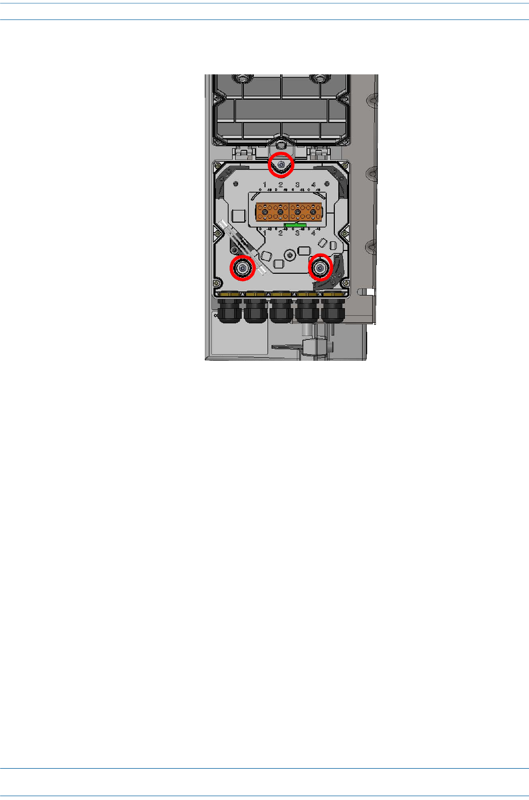
4 Attach an M4 x 25 pan-head screw to the upper hole, and two M4 x 25 pan-head screws to the holes in the
lower corners of the Splice Box.
5 Close the Splice Box.
6 Replace the six neck screws that you removed from the front cover of the Splice Box in Step 2 on page 47.
7 Go to "Grounding the CAP MX” on page 51.