
Installation Guide


Table Of Contents
- Table of Contents
- Document Overview
- ERA System Overview
- CAP MX Overview
- Safely Working with ERA Hardware
- Installing CAP MXs
- CAP MX Installation and Cascade Rules
- Cat6A Cable Requirements for Ethernet Devices
- Prepare for Installation
- Wire an Optional Hybrid Fiber Splice Box
- Mount the CAP MX
- Grounding the CAP MX
- Connect the CAP MX Cables
- Power the CAP MX
- Contacting CommScope
- CMS Global Technical Support
- Waste Electrical and Electronic Equipment Recycling
- Hardware to Software Mapping Information
- CMS Technical Training
- Accessing ERA User Documentation
CommScope ERA
®
CAP MX Medium Power Carrier Access Point Installation Guide M0203A5A_uc
Page 44 © November 2020 CommScope, Inc.
Installing CAP MXs
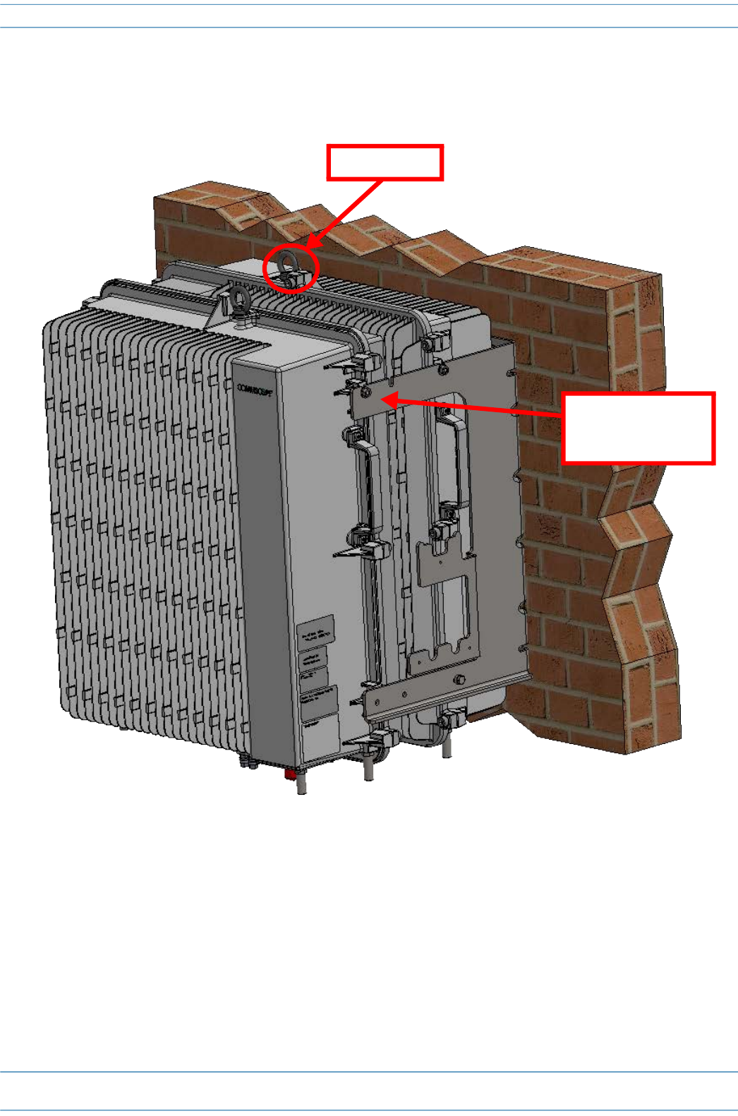
14 Use both handles, and/or the provided lifting eye, on the CAP MX-2 chassis to lift it above the Mounting
Bracket with the back of its chassis facing the back of CAP MX-1, and lower it into place, allowing the M6
pins to rest in the slots of the mounting bracket as shown below.
15 On the right side of the CAP MX-2, secure the CAP MX to the Mounting Bracket by torquing the M6 nut to
11 N-m (100 in-lbs).
16 Repeat Step 15 on the left side of the CAP MX.
Allow M6 pins to
rest in mounting
bracket slots
Lifting eye