
Installation Guide


Table Of Contents
- Table of Contents
- Document Overview
- ERA System Overview
- CAP MX Overview
- Safely Working with ERA Hardware
- Installing CAP MXs
- CAP MX Installation and Cascade Rules
- Cat6A Cable Requirements for Ethernet Devices
- Prepare for Installation
- Wire an Optional Hybrid Fiber Splice Box
- Mount the CAP MX
- Grounding the CAP MX
- Connect the CAP MX Cables
- Power the CAP MX
- Contacting CommScope
- CMS Global Technical Support
- Waste Electrical and Electronic Equipment Recycling
- Hardware to Software Mapping Information
- CMS Technical Training
- Accessing ERA User Documentation
M0203A5A_uc CommScope ERA
®
CAP MX Medium Power Carrier Access Point Installation Guide
© November 2020 CommScope, Inc. Page 41
Installing CAP MXs
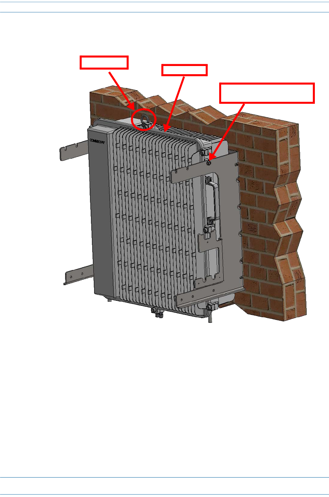
8 Use both handles, and/or the provided lifting eye, on the CAP MX-1 chassis to lift it above the Mounting
Bracket, and with the front of the chassis facing the mounting surface, lower it into place, allowing the M6
pins to rest in the slots of the mounting bracket as shown below.
9 On the right side of the CAP MX-1, torque the M6 pin to 11 N-m (100 in-lbs).
10 Repeat Step 9 on the left side of the CAP MX.
CAP MX-1
Allow M6 pins to rest in
mounting bracket slots
Lifting eye