
Installation Guide


Table Of Contents
- Table of Contents
- Document Overview
- ERA System Overview
- CAP MX Overview
- Safely Working with ERA Hardware
- Installing CAP MXs
- CAP MX Installation and Cascade Rules
- Cat6A Cable Requirements for Ethernet Devices
- Prepare for Installation
- Wire an Optional Hybrid Fiber Splice Box
- Mount the CAP MX
- Grounding the CAP MX
- Connect the CAP MX Cables
- Power the CAP MX
- Contacting CommScope
- CMS Global Technical Support
- Waste Electrical and Electronic Equipment Recycling
- Hardware to Software Mapping Information
- CMS Technical Training
- Accessing ERA User Documentation
M0203A5A_uc CommScope ERA
®
CAP MX Medium Power Carrier Access Point Installation Guide
© November 2020 CommScope, Inc. Page 39
Installing CAP MXs
3 Refer to "Determine the Mounting Site” on page 23 to determine the mounting location, which must be
able to support the weight and dimensions of the CAP MX.
4 Refer to "Mounting Orientation” on page 31 to determine the mounting orientation of the CAP MX.
5 Refer to and observe all cautions listed in "General Mounting Cautions” on page 30.
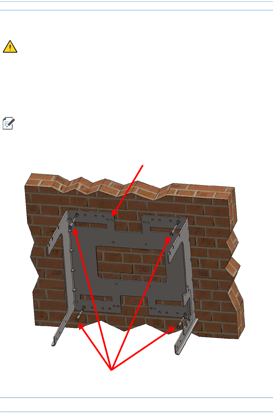
6 Secure the Mounting Bracket to the wall (or another suitable vertical surface) as shown below.
a Install the mounting bracket using 4 corrosion resistant M6 to M8 (1/4 to 5/16 inch) fasteners
according to the drilling layout.
b Confirm that the bracket is securely fastened to the wall.
Installer must verify that the mounting surface will safely support the combined load of the electronic
equipment and all attached hardware and components.
The M6 to M8 fastening system does not ship with the CAP MX as the anchor type is dependent on the
on-site conditions (wall structure and materials). Use a corrosion resistant fastening system that is
designed for the mounting substrate.
Dual Mounting Bracket
Screw anchors