
Installation Guide


Table Of Contents
- Table of Contents
- Document Overview
- ERA System Overview
- CAP MX Overview
- Safely Working with ERA Hardware
- Installing CAP MXs
- CAP MX Installation and Cascade Rules
- Cat6A Cable Requirements for Ethernet Devices
- Prepare for Installation
- Wire an Optional Hybrid Fiber Splice Box
- Mount the CAP MX
- Grounding the CAP MX
- Connect the CAP MX Cables
- Power the CAP MX
- Contacting CommScope
- CMS Global Technical Support
- Waste Electrical and Electronic Equipment Recycling
- Hardware to Software Mapping Information
- CMS Technical Training
- Accessing ERA User Documentation
CommScope ERA
®
CAP MX Medium Power Carrier Access Point Installation Guide M0203A5A_uc
Page 28 © November 2020 CommScope, Inc.
Installing CAP MXs
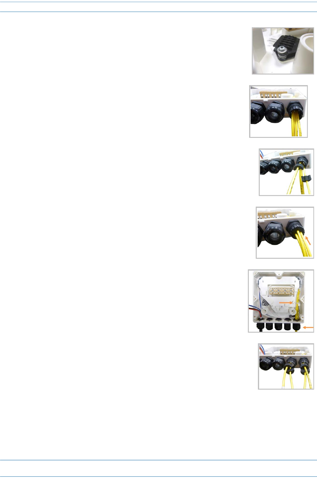
10 If a second splice holder is needed, it can be assembled using the M4
insulating washer and two M4 plain washers, as shown to the right. The
required screw is a PTK30 x 12.
11 Remove the sealing nut and rubber of the cable gland and insert the
optical cables.
12 Place each cable into one of the grooves of the seal insert.
13 Press the seal insert into the clamp ring opening.
14 Fix the optical cables inside the box using one cable tie and tight the
sealing nut.
15 It is possible to separate the optical cables and use two different cable
glands. Remove the sealing nut and rubber on each cable gland.