
Installation Guide


Table Of Contents
- Table of Contents
- Document Overview
- ERA System Overview
- CAP MX Overview
- Safely Working with ERA Hardware
- Installing CAP MXs
- CAP MX Installation and Cascade Rules
- Cat6A Cable Requirements for Ethernet Devices
- Prepare for Installation
- Wire an Optional Hybrid Fiber Splice Box
- Mount the CAP MX
- Grounding the CAP MX
- Connect the CAP MX Cables
- Power the CAP MX
- Contacting CommScope
- CMS Global Technical Support
- Waste Electrical and Electronic Equipment Recycling
- Hardware to Software Mapping Information
- CMS Technical Training
- Accessing ERA User Documentation
M0203A5A_uc CommScope ERA
®
CAP MX Medium Power Carrier Access Point Installation Guide
© November 2020 CommScope, Inc. Page 27
Installing CAP MXs
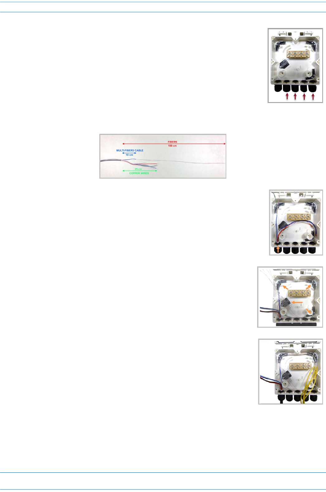
5 From the Hybrid Fiber Splice Box Kit, insert Fiber Patch Cord in one of the
cable glands indicated in the graphic to the right.
6 Strip the insulation of the composite cable for 100 cm and the fibers for 90 cm, and then shorten the
copper cables to 25 cm.
7 Insert the composite cable in the first cable gland and separate the
multi-fibers cable from the copper wires. It is necessary to remove the
nut to perform this action. The cable must be fed through the nut and it
must be retightened once finished.
8 Bend the spliced fibers using the corner guides and fix the splices to the
splice holder.
9 Bend the optical cables as shown in the graphic to the right.