
Installation Guide


Table Of Contents
- Table of Contents
- Document Overview
- ERA System Overview
- CAP MX Overview
- Safely Working with ERA Hardware
- Installing CAP MXs
- CAP MX Installation and Cascade Rules
- Cat6A Cable Requirements for Ethernet Devices
- Prepare for Installation
- Wire an Optional Hybrid Fiber Splice Box
- Mount the CAP MX
- Grounding the CAP MX
- Connect the CAP MX Cables
- Power the CAP MX
- Contacting CommScope
- CMS Global Technical Support
- Waste Electrical and Electronic Equipment Recycling
- Hardware to Software Mapping Information
- CMS Technical Training
- Accessing ERA User Documentation
M0203A5A_uc CommScope ERA
®
CAP MX Medium Power Carrier Access Point Installation Guide
© November 2020 CommScope, Inc. Page 13
CAP MX Overview
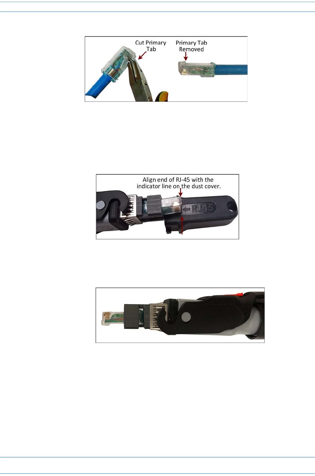
2 Remove the primary tab of the RJ-45 connector using wire cutters.
Figure 10. RJ-45 Primary Tab Removal
3 Insert the RJ-45 connector into the OCTIS connector shell as described in the“OCTIS RJ45 Reverse Lever
Assembly Instructions” on page 11 or in the printout included with the connector.
4 Use the OCTIS dust cover to verify that the RJ-45 connector extends the correct distance beyond the shell
using the indicator line on the dust cover.
Figure 11. RJ-45 Dust Cover Alignment
5 Complete the assembly of the OCTIS connector by following the OCTIS User Instructions printout
included with the connector. The final assembly is shown in Figure 12 on page 13.
Figure 12. GigaSPEED X10D RJ-45 Correctly Installed in OCTIS Connector