CommScope ERA® CAP MX Medium Power Carrier Access Point Installation Guide Installation Guide • M0203A5A_uc • November 2020
DISCLAIMER This document has been developed by CommScope, and is intended for the use of its customers and customer support personnel. The information in this document is subject to change without notice. While every effort has been made to eliminate errors, CommScope disclaims liability for any difficulties arising from the interpretation of the information contained herein.
TABLE OF CONTENTS Document Overview .................................................................................................................................................................................. 1 Document Revision History .............................................................................................................................................................................. 1 Document Cautions and Notes.................................................................
Connect the Mains Power to the CAP MX ......................................................................................................................................... 61 Connect a Hybrid Fiber Splice Box ..................................................................................................................................................... 62 Power the CAP MX .................................................................................................................................
D OCUMENT O VERVIEW This installation guide provides a product overview of and installation instructions for the Medium Power Carrier Access Point (CAP MX), which allows transmission between CommScope ERA® equipment, antennas, and Ethernet devices (such as WiFi and IP cameras). Table 1 lists the CAP MX models that this installation guide supports. Table 1.
Document Overview Document Cautions and Notes This document may contain any of the following notes, cautions, and warning icons. The icon to the left is used to indicate a caution or warning. Cautions and warnings indicate operations or steps that could cause personal injury, induce a safety problem in a managed device, destroy or corrupt information, or interrupt or stop services. The icon to the left indicates a caution or warning that pertains to laser equipment.
Document Overview dB Decibel RF Radio Frequency dBm Decibel-milliwatts RU Rack Unit DC Direct Current SFP Small Form-Factor Pluggable EFTA European Free Trade Association SMF Single-Mode Fiber EMC Electromagnetic Compatibility TEN Transport Expansion Node EMEA Europe, Middle East, Africa UAP Universal Access Point EU European Union Vac Voltage in Alternating Current F Fahrenheit Vdc Voltage in Direct Current FCC Federal Communications Commission W Watts Gb Gigabyte WCS
ERA System Overview ERA S YSTEM O VERVIEW CommScope ERA® coordinates wireless capacity throughout the entire coverage area via a single centralized head-end location or from an operator’s existing C-RAN hub. ERA systems bring together licensed wireless and power, plus Gigabit Ethernet for WiFi into one wireless system that can scale to building size and is technology and spectrum agnostic and adaptive. An ERA system comprises the components listed below.
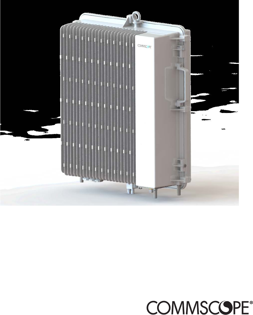
CAP MX Overview CAP MX O VERVIEW This installation guide describes the Medium Power Carrier Access Point (CAP MX), which interfaces via an optical link with a Classic CAN, or with a TEN. This allows the CAP MX to provide data over Single-Mode Fiber (SMF), or Multi-Mode Fiber (MMF). Power for CAP MXs is provided over embedded AC/DC (AC version) or remotely through hybrid fiber (DC version). On the downlink, the CAP MX converts data arriving at the CAP MX to analog signals and sends them to the Antenna port.
CAP MX Overview CAP MX Connectors and Power LED • • Figure 2 shows the connectors and Power LED on a CAP MX that has one antenna connector. Table 2 on page 7 maps the callouts in Figure 2 and describes the connectors and Power LED. Do not remove caps from any of the connectors until instructed to do so. Figure 2.
CAP MX Overview Table 2. Function of the CAP MX Connectors and LED REF # Label Description Function 1 A RJ45 Auxiliary Port Connects to external Ethernet devices such as WiFi and IP cameras. Cabling is via the appropriate CAT cable for the protocol; this model supports a 1000 BASE-T and 802.3at Class 3 Power over Cat6A Ethernet connection. Maximum attached cable length is 3 meters (9.8 feet). For information on the Auxiliary port in cascades, see "CAP MX Installation and Cascade Rules” on page 20.
CAP MX Overview Hybrid Fiber Splice Box The Hybrid Fiber Splice Box (CommScope PN 7693816-xx) separates the power from the fiber signals on a hybrid fiber feed from the Classic CAN or TEN. It feeds power to the CAP MX through a composite cable that includes both fiber and copper power wires. Fiber and copper terminate at the Splice Box, which allows you to separate the DC wires and fiber at the remote end.
CAP MX Overview Figure 3. OCTIS SFP+ Reverse Lever Assembly Instructions (PN: 7770612) M0203A5A_uc © November 2020 CommScope, Inc.
CAP MX Overview Figure 4. OCTIS SFP+ Reverse Lever Mating Instructions (PN: 7770612) Figure 5. OCTIS SFP+ Reverse Lever Replacement Instructions (PN: 7770612) CommScope ERA® CAP MX Medium Power Carrier Access Point Installation Guide Page 10 M0203A5A_uc © November 2020 CommScope, Inc.
CAP MX Overview OCTIS RJ45 Reverse Lever Assembly Instructions Scan the QR code to the right to watch the OCTIS RJ45 connector assembly video. CommScope GigaSPEED X10D RJ-45 Connector tabs must be removed BEFORE inserting the them into the OCTIS connectors. For installation instructions, see “Special Instructions for GigaSPEED X10D Connectors” on page 12. Figure 6. OCTIS RJ-45 Reverse Lever Assembly Instructions (PN: 7760652) M0203A5A_uc © November 2020 CommScope, Inc.
CAP MX Overview Figure 7. OCTIS RJ-45 Reverse Lever (PN: 7760652) Mating Instructions Special Instructions for GigaSPEED X10D Connectors The GigaSPEED X10D 3095B CAT6A cable has a primary and an additional secondary locking tab. If the RJ-45 connector is inserted in the OCTIS shell with the tabs intact, the connector will fit but it may get stuck inside the shell. To prevent this, both of these locking tabs must be removed before insertion into the OCTIS connector shell. Figure 8.
CAP MX Overview 2 Remove the primary tab of the RJ-45 connector using wire cutters. Figure 10. RJ-45 Primary Tab Removal 3 4 Insert the RJ-45 connector into the OCTIS connector shell as described in the“OCTIS RJ45 Reverse Lever Assembly Instructions” on page 11 or in the printout included with the connector. Use the OCTIS dust cover to verify that the RJ-45 connector extends the correct distance beyond the shell using the indicator line on the dust cover. Figure 11.
Safely Working with ERA Hardware S AFELY W ORKING WITH ERA H ARDWARE The following sections provide important information that you should read and know before working with any ERA hardware. Observe all cautions and warnings listed in this section. RF Safety Cautions This system is a RF Transmitter and continuously emits RF energy. Maintain a minimum clearance from the antenna as specified in Table 5 on page 19 while the system is operating.
Safely Working with ERA Hardware Property Damage Warnings Keep operating instructions within easy reach and make them available to all users. Only license holders for the respective frequency range are allowed to operate this unit. Read and obey all the warning labels attached to the unit. Make sure that all warning labels are kept in a legible condition. Replace any missing or damaged labels.
Safely Working with ERA Hardware The CAP MX is to be used only with CommScope (NEC Class 2) or Limited Power Source ERA Subrack, or equivalent. Read and observe all the warning labels attached to the unit. Make sure that all warning labels are kept in a legible condition. Replace any missing or damaged labels. Guard Against Damage from Electro-Static Discharge Electro-Static Discharge (ESD) can damage electronic components.
Safely Working with ERA Hardware 4 Notice: For installations which have to comply with FCC/ISED requirements: English: This device complies with FCC Part 15. Operation is subject to the following two conditions: (1) this device may not cause interference, and (2) this device must accept any interference, including interference that may cause undesired operation of the device. This device complies with Health Canada's Safety Code.
Safely Working with ERA Hardware 6 7 For Canada and US, components used to reduce the Overvoltage Category shall comply with the requirements of IEC 61643-series. As an alternative, components used to reduce the Overvoltage Category may comply with ANSI/IEEE C62.11, CSA Certification Notice No. 516, CSA C22.2 No. 1, or UL 1449. Suitability of the component for the application shall be determined for the intended installation. Notice: Corresponding local particularities and regulations must be observed.
Safely Working with ERA Hardware Table 4. Compliance Labels Symbol Compliance Meaning WARNING: This is NOT a CONSUMER device. It is designed for installation by an installer approved by an ISED licensee. You MUST have an ISED LICENCE or the express consent of an ISED licensee to operate this device. — ISED CE AVERTISSEMENT: Ce produit N'EST PAS un appareil de CONSOMMATION. Il est conçu pour être installé par un installateur approuvé par un titulaire de licence d'ISDE.
Installing CAP MXs I NSTALLING CAP MX S The following sections guide you through the installation of a CAP MX. Pay attention to all cautions and follow the steps in the order presented. CAP MX APs require the use of RFD Card PN 7633229-01 or 7633229-02 or higher. CAP MX Installation and Cascade Rules When cascading a Secondary CAP MX or an external Ethernet device such as WiFi or an IP camera, you must observe the following rules.
Installing CAP MXs Cat6A Cable Requirements for Ethernet Devices If you connect an Ethernet device to a Fiber CAP MX, you must observe the following rules. • • • • • Plenum rated cable must be used whenever it is required by local electrical codes. Shielded twisted pair is not required unless operating in a high RFI/EMI environment. CommScope strongly recommends using factory terminated and tested Cat6A Patch Cord.
Installing CAP MXs Determine the Power Consumption of the CAP MX Use the power consumption matrix in Table 7 to calculate power consumption for a CAP MX, where • • the consumption numbers are at the CAP MX power inputs and do not account for feed losses the maximum consumption numbers in Table 7 do not include the power consumed by any attached auxiliary devices. Both CAP MX power consumption and auxiliary device power must be included when calculating feed losses. Table 7.
Installing CAP MXs Determine the Mounting Site When deciding on a suitable mounting site, observe the following rules; refer also to "Mounting Orientation” on page 31. • • The CAP MX is suitable for installation indoors or outdoors. Use the weights listed in Table 8 to determine a site that can bear the weight of the CAP MX that is being installed, where: – – The “Maximum Lift Weight” is the highest weight that must be lifted during installation.
Installing CAP MXs Figure 13. Mounting Dimensions for Single Mounting Bracket CommScope ERA® CAP MX Medium Power Carrier Access Point Installation Guide Page 24 M0203A5A_uc © November 2020 CommScope, Inc.
Installing CAP MXs Figure 14. Mounting Dimensions for the Dual Mounting Bracket M0203A5A_uc © November 2020 CommScope, Inc.
Installing CAP MXs Unpack and Inspect the CAP MX and Optional Accessories 1 2 3 4 Inspect the exterior of the shipping container(s) for evidence of rough handling that may have damaged the components in the container. Unpack each container while carefully checking the contents for damage and verify with the packing slip. If damage is found or parts are missing, file a claim with the commercial carrier and notify CommScope Technical Support (see "CMS Global Technical Support” on page 63).
Installing CAP MXs 5 From the Hybrid Fiber Splice Box Kit, insert Fiber Patch Cord in one of the cable glands indicated in the graphic to the right. 6 Strip the insulation of the composite cable for 100 cm and the fibers for 90 cm, and then shorten the copper cables to 25 cm. 7 Insert the composite cable in the first cable gland and separate the multi-fibers cable from the copper wires. It is necessary to remove the nut to perform this action.
Installing CAP MXs 10 If a second splice holder is needed, it can be assembled using the M4 insulating washer and two M4 plain washers, as shown to the right. The required screw is a PTK30 x 12. 11 Remove the sealing nut and rubber of the cable gland and insert the optical cables. 12 Place each cable into one of the grooves of the seal insert. 13 Press the seal insert into the clamp ring opening. 14 Fix the optical cables inside the box using one cable tie and tight the sealing nut.
Installing CAP MXs 16 Close all unused grooves with the plastic cylinders, no matter if one or two cable glands are used. 17 Insert the copper wires in the first multiple terminal connectors. See markings on the internal support. Then fasten the copper cables inside the box using one cable tie. 18 Remove the sealing nut and insert the CAP MX supply cable and tighten the sealing nut. 19 Connect the supply cable to the terminal strip and fix it inside the box using one cable tie.
Installing CAP MXs Mount the CAP MX The CAP MX is suitable for indoor and outdoor installations. General Mounting Cautions The following cautions apply to all CAP MX installations; there may be other mounting cautions applicable to a specific mounting option, which will be defined in the applicable mounting procedure. Attach all CAP MXs securely to a stationary object as described in this installation guide. To maintain proper ventilation, keep at least 76 mm (3-inch) clearance around the CAP MX.
Installing CAP MXs Mounting Orientation CAP MXs are passively cooled and must therefore always be mounted with its ANT port pointing down, as shown in Figure 15. ANT port pointing down Figure 15. Mounting Orientation for a CAP MX M0203A5A_uc © November 2020 CommScope, Inc.
Installing CAP MXs Mount the CAP MX to a Wall or Vertical Surface There are two mounting options for the CAP MX; follow the procedure that is appropriate for this installation: • • "Mount a CAP MX Using a Single Mounting Bracket” on page 32 "Mount Two CAP MXs Using a Dual Mounting Bracket” on page 38.
Installing CAP MXs 6 Secure the Mounting Bracket to the wall (or another suitable vertical surface) as shown below. a Install the mounting bracket using 4 corrosion resistant M6 to M8 (1/4 to 5/16 inch) fasteners according to the drilling layout. The M6 to M8 fastening system does not do not ship with the CAP MX as the anchor type is dependent on the on-site conditions (wall structure and materials). Use a corrosion resistant fastening system that is designed for the mounting substrate.
Installing CAP MXs 7 From both sides of the CAP MX: a b Loosen the M6 lock nuts, as shown below, to provide adequate space for the mounting bracket. Remove the two M6 screws and their M6 plain and M6 split-lock washers; reserve the screws and washers as you will later reinstall them. Remove M6x12 bolt and washers CommScope ERA® CAP MX Medium Power Carrier Access Point Installation Guide Page 34 M0203A5A_uc © November 2020 CommScope, Inc.
Installing CAP MXs 8 Use both handles and/or the provided lifting eye on the CAP MX to lift it above the Mounting Bracket and then lower it into place. Lifting eye M0203A5A_uc © November 2020 CommScope, Inc.
Installing CAP MXs 9 On the right side of the CAP MX secure the CAP MX to the Mounting Bracket by torquing the M6 nut to 11 N-m (100 in-lbs). M6 nut 10 Repeat Step 9 on the left side of the CAP MX. CommScope ERA® CAP MX Medium Power Carrier Access Point Installation Guide Page 36 M0203A5A_uc © November 2020 CommScope, Inc.
Installing CAP MXs 11 On lower right of the CAP MX, reinstall the M6x12 screw and its washers that you removed in Step 7 on page 34. a b Slide first the M6 plain washer and then the M6 split-lock washer over the M6x12 screw. Insert the M6x12 screw through the screw hole shown below, and screw it back into the CAP MX chassis; torque to 11 N-m (100 n-lbs). M6x12 bolt and washer set 12 13 Repeat Step 11 on the left side of the CAP MX.
Installing CAP MXs Mount Two CAP MXs Using a Dual Mounting Bracket In this procedure you will mount two CAP MXs back-to-back in one Dual Mounting Bracket. The steps in this procedure will identify the two CAP MXs as CAP MX-1 and CAP MX-2, as shown in Figure 16. CAP MX-1 (front of CAP MX-1 faces the mounting surface) Figure 16. Two CAP MXs Back-to-Back in a Dual Mounting Bracket Do the following to mount two CAP MXs in a Dual Mounting Bracket.
Installing CAP MXs 3 Refer to "Determine the Mounting Site” on page 23 to determine the mounting location, which must be able to support the weight and dimensions of the CAP MX. Installer must verify that the mounting surface will safely support the combined load of the electronic equipment and all attached hardware and components. 4 5 6 Refer to "Mounting Orientation” on page 31 to determine the mounting orientation of the CAP MX.
Installing CAP MXs 7 From both sides of CAP MX-1: a b Loosen the M6 lock nuts, as shown below, to provide adequate space for the mounting bracket. Remove the two M6 screws and their M6 plain and M6 split-lock washers; reserve the screws and washers as you will later reinstall them. Loosen M6 pin Remove M6x12 bolt and the washers CommScope ERA® CAP MX Medium Power Carrier Access Point Installation Guide Page 40 M0203A5A_uc © November 2020 CommScope, Inc.
Installing CAP MXs 8 Use both handles, and/or the provided lifting eye, on the CAP MX-1 chassis to lift it above the Mounting Bracket, and with the front of the chassis facing the mounting surface, lower it into place, allowing the M6 pins to rest in the slots of the mounting bracket as shown below. Lifting eye CAP MX-1 Allow M6 pins to rest in mounting bracket slots 9 10 On the right side of the CAP MX-1, torque the M6 pin to 11 N-m (100 in-lbs). Repeat Step 9 on the left side of the CAP MX.
Installing CAP MXs 11 On lower right of the CAP MX-1, reinstall the M6x12 screw and its washers that you removed in Step 7 on page 40. a b Slide first the M6 split-lock washer and then the M6 plain washer over the M6x12 screw. Insert the M6x12 screw through the screw hole shown below, and screw it back into the CAP MX-1 chassis; torque to 11 N-m (100 in-lbs). M6x12 bolt and washer set in hole closest to mounting surface 12 Repeat Step 11 on the left side of the CAP MX-1.
Installing CAP MXs 13 From both sides of CAP MX-2: a b Loosen the M6 lock nuts, as shown below, to provide adequate space for the mounting bracket. Remove the two M6 screws and their washers; reserve the screws and washers as you will later reinstall them. Loosen M6 pin Remove M6x12 bolt and the washers M0203A5A_uc © November 2020 CommScope, Inc.
Installing CAP MXs 14 Use both handles, and/or the provided lifting eye, on the CAP MX-2 chassis to lift it above the Mounting Bracket with the back of its chassis facing the back of CAP MX-1, and lower it into place, allowing the M6 pins to rest in the slots of the mounting bracket as shown below. Lifting eye Allow M6 pins to rest in mounting bracket slots 15 16 On the right side of the CAP MX-2, secure the CAP MX to the Mounting Bracket by torquing the M6 nut to 11 N-m (100 in-lbs).
Installing CAP MXs 17 On lower right of the CAP MX-2, reinstall the M6x12 screw and its washers that you removed in Step 13 on page 43. a b Slide first the M6 split-lock washer and then the M6 plain washer over the M6x12 screw. Insert the M6x12 screw through the screw hole shown below, and screw it back into the CAP MX chassis; torque to 11 N-m (100 in-lbs). M6x12 bolt and washer set in hole furthest from the mounting surface 18 19 Repeat Step 11 on the left side of CAP MX-2.
Installing CAP MXs Attach a Hybrid Fiber Splice Box to the CAP MX The steps in this section pertain only to those installations that require the use of the optional Hybrid Fiber Splice Box to provide fiber and power to the CAP MX. If the optional Hybrid Fiber Splice Box is not required for this installation, skip to "Grounding the CAP MX” on page 51.
Installing CAP MXs 2 Remove the six neck screws (shown below) from the front cover of the Splice Box. 3 Open the Splice Box. M0203A5A_uc © November 2020 CommScope, Inc.
Installing CAP MXs 4 Attach an M4 x 25 pan-head screw to the upper hole, and two M4 x 25 pan-head screws to the holes in the lower corners of the Splice Box. 5 Close the Splice Box. 6 7 Replace the six neck screws that you removed from the front cover of the Splice Box in Step 2 on page 47. Go to "Grounding the CAP MX” on page 51. CommScope ERA® CAP MX Medium Power Carrier Access Point Installation Guide Page 48 M0203A5A_uc © November 2020 CommScope, Inc.
Installing CAP MXs Attaching a Hybrid Fiber Splice Box for a Dual Mount Installation 1 2 Break the left-hand side hook of the Splice Box bracket. This is necessary for proper mounting. Hang the Splice Box onto the Dual Mounting Bracket on the left-hand side of the CAP MX, as shown below. Dual Mounting Bracket Hybrid Fiber Splice Box M0203A5A_uc © November 2020 CommScope, Inc.
Installing CAP MXs 3 Remove the six neck screws (shown below) from the front cover of the Splice Box. 4 Open the Splice Box. 5 6 7 8 Attach an M4 x 25 pan-head screw to the upper hole, and two M4 x 25 pan-head screws to the holes in the lower corners of the Splice Box. Close the Splice Box. Replace the six neck screws that you removed from the front cover of the Splice Box in Step 3 on page 50. Go to "Grounding the CAP MX” on page 51.
Installing CAP MXs Grounding the CAP MX The CAP MX must be provided with a permanently connected protective earthing conductor. This conductor must be installed by a skilled person. Do not use the grounding bolts to connect an external device. 1 Connect an earth-bonding cable to the grounding bolt connections on the outside of the CAP MX chassis, as shown below. 2 Loosen the M6 hex nut(s), and then connect the earth-bonding cable between the two washers as shown to the right.
Installing CAP MXs Connect the CAP MX Cables Complete the following procedures in the order in which they are presented. Unless otherwise noted, each procedure is applicable to a singular CAP MX (not in a cascade), or to a Primary or Secondary CAP MX in a cascade.
Installing CAP MXs Obtain the Required Cable Material Contact your local CommScope sales representative to obtain the following components, as required, for this installation. • • • Per the installation plan, obtain either Single Mode Fiber (SMF) or Multi Mode Fiber (MMF) that is of sufficient length to reach from the CAP MX to the Classic CAN or TEN. Obtain at least one Optical OCTIS Kit (PN 7770612). All installations require one Optical OCTIS Kit, which is included in the CAP MX shipment.
Installing CAP MXs Connect the CAP MX to an RF Antenna The following sections guide you through connecting the CAP MX; complete these procedures in the order in which they are presented. • • "Clean the RF Cable Connectors” on page 54 "Connect the Antenna Cable(s)” on page 57. Clean the RF Cable Connectors This section tells you how to clean RF cable connectors. The graphics in this section illustrate the cleaning procedure and do not show the CAP MX. This procedure requires the use of compressed air.
Installing CAP MXs 3 Use compressed air to remove metal chips and small particles from the mating and inner surfaces of the connector. 4 Use a lint-free wipe drenched with isopropyl alcohol to clean the connector winding. 5 Use a cotton bud drenched with isopropyl alcohol to clean the lip of the inner ring. 6 Use a cotton bud drenched with isopropyl alcohol to clean the inside surface of the inner ring.
Installing CAP MXs 8 Remove the protective caps from the unit connector, and then clean it the same way that you cleaned the cable connector. 9 Use compressed air to remove metal chips and small particles from the mating and inner surfaces of the connector. 10 Use a lint-free wipe drenched with isopropyl alcohol to clean the winding area. 11 Use a cotton bud drenched with isopropyl alcohol to clean the inside mating surface of the inner ring.
Installing CAP MXs Connect the Antenna Cable(s) The following information regarding antenna mapping and is relevant to all CAP MX variants. • • For Non-MIMO bands, there is no channel mapping option for the transceiver/antenna port. The transceiver/antenna port relationship is fixed in hardware. For MIMO bands, the ERA GUI maps MIMO channels according to their AP designation: – – • AP0 to antenna port ANT1 AP1 to antenna port ANT2.
Installing CAP MXs Connect the CAP MX to a Classic CAN or TEN Connect the CAP MX Optical Port 1 as appropriate for this installation. Note the maximum range listed in Table 11. 1 2 3 4 5 Remove the dust cap from the CAP MX Optical Port 1 connector and the connectors on the SMF or MMF. Follow the local cleaning technique to clean the optical port for each SFP+ Module. Clean the connectors on the SMF or MMF following the fiber supplier’s recommendations.
Installing CAP MXs 4 Install an Ethernet OCTIS Kit on the end of the CAT cable that will connect to the Fiber CAP MX, and then connect that end of the cable to Port A on the Fiber CAP MX. (Refer to the technical data sheet that ships with the OCTIS Kit for further information.) Cat6A, including all Cat6A cables, Cat6A Patch Cords, and Patch Panels, between Port A on the Fiber CAP MX and an auxiliary Ethernet device cannot exceed 3 meters (9.8 feet).
Installing CAP MXs Amphenol Protec ve 4-Pin female cap connector 3x end splice Black White Green 4 3 1 2 CAP MX DC Power Cable CAP M Mains connector Figure 17. CAP MX AC Power Cable The standard CAP MX DC power cable is a 3.2 m (10.5 ft) 13 AWG cable with a 4-pin Amphenol C016 series plug on one end to connect to the CAP MX Mains connector. The other end of the cable is unterminated with 2 end splices to connect to the -48 Vdc power source. The standard DC power cable is shown in Figure 18.
Installing CAP MXs Connect the Mains Power to the CAP MX 1 2 Locate the Mains power cable that was delivered with the CAP MX. Locate or install a suitable power junction box or receptacle near the unit and route the power cable from the power source to the CAP MX. Do not connect the cable to the unit's Mains connector at this time. The power source must be interruptible. The Mains cable must be properly secured observing local regulations and electrical codes.
Installing CAP MXs Connect a Hybrid Fiber Splice Box For a CAP MX powered by the Hybrid Fiber Splice Box (PN 7693816-xx): • • • connect the power cable to the proprietary 4-pin, 36 to 60 Vdc Power connector on the CAP MX, and terminate the other end to the CAP MX Hybrid Fiber Splice Box. Install an SFP+ module of the desired type (same as used at the OPT Card port) into the OCTIS connector before connecting the LC Fiber pigtail.
Contacting CommScope C ONTACTING C OMM S COPE The following sections tell you how to contact CommScope for additional information or for assistance. CMS G LOBAL T ECHNICAL S UPPORT The following sections tell you how to contact the CommScope Mobility Solutions (CMS) Technical Support team. Support is available 7 days a week, 24 hours a day. Telephone Helplines Use the following Helpline telephone numbers to get live support, 24 hours a day: 24x7 +1 888-297-6433 (Toll free for U.S.
Hardware to Software Mapping Information H ARDWARE 1 2 TO S OFTWARE M APPING I NFORMATION Scan the QR Code to the right to view or download the minimum software requirements for each of the DCCS hardware modules. Alternatively, you can go to the following web address to access the portal: http://www.commscope.com/resources/in-building-wireless Click on a document link to open it, or right click on the link and select the Save target as… option from the contextual menu.
Accessing ERA User Documentation A CCESSING ERA U SER D OCUMENTATION 1 Scan the QR Code to the right to go to the CommScope DCCS Customer Portal, where you can access the DCCS user documentation. Alternatively, you can go to the following web address to access the portal: 2 http://www.commscope.com/membership Access to the Customer Portal requires a user account and password.
Accessing ERA User Documentation CommScope ERA® CAP MX Medium Power Carrier Access Point Installation Guide Page 66 M0203A5A_uc © November 2020 CommScope, Inc.