
Installation Guide


M0201AJG_uc CommScope ERA
®
Medium Power Carrier Access Point Installation Guide
© Decemeber 2020 CommScope, Inc. Page 19
Safely Working with ERA Hardware
autre antenne ou emetteur. Les utilisateurs et les installateurs doivent etre fournis avec des instructions
d'installation de l'antenne et des conditions de fonctionnement de l'emetteur pour satisfaire la
conformite aux expositions RF.
5 Notice: The maximum antenna gain allowed per band for a CAP M 6/6/7E/7E is listed in Table 4 below.
According to KDB 662911 "D01 Multiple Transmitter Output v02r01":
• Pout = max RF output power settable each port = 29 dBm
• N
ANT = number of outputs = 2
• 10 log(N
ANT) dB = RF output summed (in MIMO configuration) = 3 dB
• G
A
= antenna gain = 4 dBi (not cross-polarized)
• G
D
= directional gain (both transmit signals are correlated) = GA + 10 log(NANT) dBi (= GA when
transmit signals are completely uncorrelated) = 7 dBi
• G
L
= insertion loss (TX-to-antenna attenuation) = 1.5 dB (note that this value is highly conservative,
because is higher in real installations)
Formula
: Pout + 10 log(NANT) dB + G
D
- G
L
< 5 W
ERP
(39.14 dBm eirp)
29dBm + 3 dB + 7dbi - 1.5dB = 37.5 dBm eirp
Cross-polarized antennas with N
ANT = 2: in the case of a transmitter with only two outputs driving a pair
of antennas that are cross-polarized, directional gain is the gain of an individual antenna. If the two
antennas have different gains, the larger gain applies.
6 Notice: The unit complies with Overvoltage Category II. It also complies with the surge requirement
according to EN 61000-4-5 (fine protection); however, installation of an additional medium (via local
supply connection) and/or coarse protection (external surge protection) is recommended depending on
the individual application in order to avoid damage caused by overcurrent.
For Canada and US, components used to reduce the Overvoltage Category shall comply with the
requirements of IEC 61643-series. As an alternative, components used to reduce the Overvoltage
Category may comply with ANSI/IEEE C62.11, CSA Certification Notice No. 516, CSA C22.2 No. 1, or UL
1449. Suitability of the component for the application shall be determined for the intended installation.
7 Notice: Corresponding local particularities and regulations must be observed. For national deviations,
please refer to the respective documents, which are available from CommScope.
8 Note: This unit complies with European standard EN60950-1 / EN62368-1.
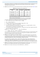
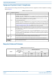
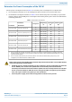
Table 4. Maximum Antenna Gain CAP M 6/6/7E/7E
FREQUENCY BAND
(MHz)
POWER
(dBm)
LINEAR ANTENNA
GAIN (dBi)
CROSS-POLARIZED
ANTENNA GAIN (dBi)
617.0 - 652.0 29 7* 10*
729.0 - 746.0 29 7* 10*
746.0 - 756.0 29 7* 10*
758.0 - 768.0 29 7* 10*
* The LINEAR ANTENNA GAIN and CROSS-POLARIZED ANTENNA GAIN including
feeder loss must be selected so that the output power does not exceed 5 W ERP per
channel according to FCC §90.219 (d)(3)(i).