
Installation Guide

CommScope ERA
®
Medium Power Carrier Access Point Installation Guide M0201AJG_uc
Page 6 © Decemeber 2020 CommScope, Inc.
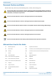
CAP M Overview
CAP M Connectors and Power LED
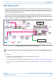
• Figure 2 shows the connectors and Power LED on a CAP M that has one antenna connector.
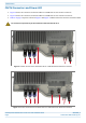
• Figure 3 shows the connectors and Power LED on a CAP M that has two antenna connectors.
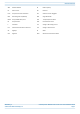
• Table 2 on page 7 maps the callouts in Figure 2 and Figure 3 and describes the connectors and Power LED.
Figure 2. Location of Connectors and Power LED on a CAP M with One Antenna Connector
Figure 3. Location of Connectors and Power LED on a CAP M with Two Antenna Connectors
Do not remove caps from any of the connectors until instructed to do so.
1 2 3 4 5a 76
1 2 3 4 5a 76
5b