
Installation Guide

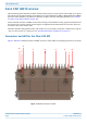
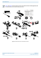


Table Of Contents
- Table of Contents
- Document Overview
- Fiber CAP M2 Overview
- Plan and Prepare for a Fiber CAP M2 Installation
- Mount the Fiber CAP M2
- Connect the Cables to the Fiber CAP M2
- Powering on a Fiber CAP M 2
- Contacting CommScope

CommScope ERA
®
CAP M2 with Fiber Interface M0203AHA_uc
Page 8 © August 2022 CommScope, Inc.
Fiber CAP M2 Overview
FIBER CAP M2 OVERVIEW
This installation guide describes the Fiber CAP M2, which interfaces with a Classic CAN or TEN via an optical
link. This allows the Fiber CAP M2 to provide data over Single-Mode Fiber (SMF) or Multi-Mode Fiber (MMF).
Power for Fiber CAP M2s is provided over External AC/DC or remotely through hybrid fiber (see "Connect
the Cables to the Fiber CAP M2” on page 28).
On the downlink, the Fiber CAP M2 converts data arriving at the CAP M2 to analog signals and sends them to
the Antenna ports. On the uplink, received signals are digitized and serialized into data streams, which are
sent back to the Classic CAN or TEN.
The Fiber CAP M2 is designed for indoor and outdoor use. It is passively cooled with a temperature range of:
-33°C to +50C (-27.4°F to +122°F); see also "Recommended Tools and Material” on page 16.
Connectors and LED for the Fiber CAP M2
Figure 1 and Table 5 identify the Fiber CAP M2 connectors and its LED; corresponding connectors are shown.
Figure 1. CAP M2 Connectors and LED
8
7
6
5
4
3
2
1
0