
Installation Guide
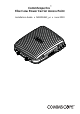
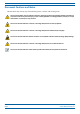
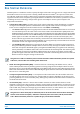
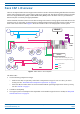
Table Of Contents
- Table of Contents
- Document Overview
- Era System Overview
- Fiber CAP L Overview
- Plan and Prepare for a Fiber CAP L Installation
- Maximum Number of Fiber CAP Ls Supported in an Era System
- Cascade Rules for Fiber CAP Ls
- Cat6A Cable Requirements for Ethernet Devices
- Safely Working with Era Hardware
- Determine the Power Consumption of the CAP L
- Determine the CAP L Installation Site
- Recommended Tools and Material
- Unpack and Inspect the CAP L and Optional Accessories
- Obtain the Required Materials
- Mount the Fiber CAP L
- General Mounting Cautions
- Mounting a CAP L with a Flat Mounting Bracket Kit
- Mounting Two CAP Ls with a Dual Mounting Kit
- Mounting a CAP L with an AC/DC Power Supply Kit
- Wiring the AC/DC Power Supply Kit.
- Mounting a CAP L with a Hybrid Fiber Splice Box Kit
- Prepare for CAP L Hybrid Fiber Splice Box Kit Installation
- Assembling and Wiring the Hybrid Fiber Splice Box
- Wire the Hybrid Fiber Splice Box
- Wire a Hybrid Fiber Splice Box for 4-Wire Power with Limited Power Source
- Wire a Hybrid Fiber Splice Box for 2-Wire Power without Limited Power Source
- Wire a Hybrid Fiber Splice Box to Cascade Two CAP Ls with the 2-Wire Power Configuration
- Wire a Hybrid Fiber Splice Box to Cascade Two CAP Ls with the 4-Wire Power Configuration
- Wall Mount a CAP L Using a CAP L Hybrid Fiber Splice Box Kit
- Ceiling Mount a CAP L
- Connect the Cables to the Fiber CAP L
- Powering on a Fiber CAP L
- CAP L Maintenance
- Contacting CommScope

M0201ANC_uc CommScope Era
™
Fiber Low Power Carrier Access Point Installation Guide
© June 2019 CommScope, Inc. Page 5
Fiber CAP L Overview
FIBER CAP L OVERVIEW
There is one Optical Fiber and two Copper CAP L interface variants. This installation guide describes the Fiber
CAP L, which interfaces with a Classic CAN or TEN via an optical link. This allows the Fiber CAP L to provide
data over Single-Mode Fiber
(SMF) or Multi-Mode Fiber (MMF). Power for Fiber CAP Ls is provided over
External AC/DC or remotely thr
ough hybrid fiber.
On the downlink, the Fiber CAP L converts data arriving at the CAP L to analog signals and sends them to the
An
tenna
ports. On the uplink, received signals are digitized and serialized into data streams, which are sent
back to the Classic CAN or TEN. Figure 1 shows how a Fiber CAP L can be deployed in an Era system.
e-POI
Classic
CAN
eNode B
TEN
UAP
UAP
UAP
UAP
* Power can be on AP side (AC or DC)
or be remote with composite fiber (DC)
TEN
Cat6A cable
Fiber
Power
Power*
Fiber CAP L
Fiber CAP L
Fiber CAP L
Fiber CAP L
Fiber CAP L
Fiber CAP L
Fiber CAP L
Fiber CAP L
Fiber CAP L
Fiber CAP L
Figure 1. Fiber CAP L in an Era System
The Fiber CAP L
• has the following temperature ranges
– without a Fan Kit, it is passively cool
ed with a temperature range of: -33°C to +40°C (-27.4°F to
104°F); see also "Extended CAP L Temperature Operation” on page 22.
– with a Fan Kit, the Fiber CAP L
has an increased maximum operating temperature of 55°C (131°F);
see also "Fan Kit” on page 7.
• is o
utdoor rated (IP67)
• has a typical power consumption that dependent on the model ranges from
92 to 103W; see "Required
Antenna Distances” on page 16.