
Installation Guide

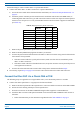
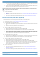

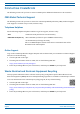

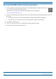
Table Of Contents
- Table of Contents
- Document Overview
- Era System Overview
- Fiber CAP L Overview
- Plan and Prepare for a Fiber CAP L Installation
- Maximum Number of Fiber CAP Ls Supported in an Era System
- Cascade Rules for Fiber CAP Ls
- Cat6A Cable Requirements for Ethernet Devices
- Safely Working with Era Hardware
- Determine the Power Consumption of the CAP L
- Determine the CAP L Installation Site
- Recommended Tools and Material
- Unpack and Inspect the CAP L and Optional Accessories
- Obtain the Required Materials
- Mount the Fiber CAP L
- General Mounting Cautions
- Mounting a CAP L with a Flat Mounting Bracket Kit
- Mounting Two CAP Ls with a Dual Mounting Kit
- Mounting a CAP L with an AC/DC Power Supply Kit
- Wiring the AC/DC Power Supply Kit.
- Mounting a CAP L with a Hybrid Fiber Splice Box Kit
- Prepare for CAP L Hybrid Fiber Splice Box Kit Installation
- Assembling and Wiring the Hybrid Fiber Splice Box
- Wire the Hybrid Fiber Splice Box
- Wire a Hybrid Fiber Splice Box for 4-Wire Power with Limited Power Source
- Wire a Hybrid Fiber Splice Box for 2-Wire Power without Limited Power Source
- Wire a Hybrid Fiber Splice Box to Cascade Two CAP Ls with the 2-Wire Power Configuration
- Wire a Hybrid Fiber Splice Box to Cascade Two CAP Ls with the 4-Wire Power Configuration
- Wall Mount a CAP L Using a CAP L Hybrid Fiber Splice Box Kit
- Ceiling Mount a CAP L
- Connect the Cables to the Fiber CAP L
- Powering on a Fiber CAP L
- CAP L Maintenance
- Contacting CommScope

M0201ANC_uc CommScope Era
™
Fiber Low Power Carrier Access Point Installation Guide
© June 2019 CommScope, Inc. Page 59
Connect the Cables to the Fiber CAP L
Connect the Passive RF Antenna
The following information regarding antenna mapping and is relevant to all Fiber CAP Ls.
• For Non-MIMO bands, there is no channel mapping option for the transceive
r/antenna port. The
transceiver/antenna port relationship is fixed in hardware.
• For MIMO bands, the Era GUI maps MIMO channels according to their AP designation:
– AP0 to antenna port ANT 1
– AP1 to antenna port ANT 2.
• When using SISO channels on a CAP L that supp
orts MIMO, the system will automatically balance the
number of channels between the two antenna ports, where the first SISO channel is mapped to ANT 1, the
second SISO channel is mapped to ANT 2, an
d so on.
9 Use compressed air to remove metal chips and small particles
from the mating and inner surfaces of the connector.
10 Use a lint-free wipe drenched with isopropyl alcohol to clean the
winding area.
11 Use a cotton bud drenched with isopropyl alcohol to clean the
inside mating surface of the inner ring.
12 Use a cotton bud drenched with isopropyl alcohol to clean the
outside surface of the center pin.