
Installation Guide
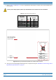
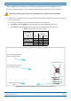
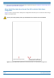
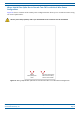
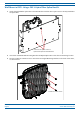
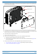
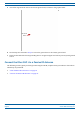
Table Of Contents
- Table of Contents
- Document Overview
- Era System Overview
- Fiber CAP L Overview
- Plan and Prepare for a Fiber CAP L Installation
- Maximum Number of Fiber CAP Ls Supported in an Era System
- Cascade Rules for Fiber CAP Ls
- Cat6A Cable Requirements for Ethernet Devices
- Safely Working with Era Hardware
- Determine the Power Consumption of the CAP L
- Determine the CAP L Installation Site
- Recommended Tools and Material
- Unpack and Inspect the CAP L and Optional Accessories
- Obtain the Required Materials
- Mount the Fiber CAP L
- General Mounting Cautions
- Mounting a CAP L with a Flat Mounting Bracket Kit
- Mounting Two CAP Ls with a Dual Mounting Kit
- Mounting a CAP L with an AC/DC Power Supply Kit
- Wiring the AC/DC Power Supply Kit.
- Mounting a CAP L with a Hybrid Fiber Splice Box Kit
- Prepare for CAP L Hybrid Fiber Splice Box Kit Installation
- Assembling and Wiring the Hybrid Fiber Splice Box
- Wire the Hybrid Fiber Splice Box
- Wire a Hybrid Fiber Splice Box for 4-Wire Power with Limited Power Source
- Wire a Hybrid Fiber Splice Box for 2-Wire Power without Limited Power Source
- Wire a Hybrid Fiber Splice Box to Cascade Two CAP Ls with the 2-Wire Power Configuration
- Wire a Hybrid Fiber Splice Box to Cascade Two CAP Ls with the 4-Wire Power Configuration
- Wall Mount a CAP L Using a CAP L Hybrid Fiber Splice Box Kit
- Ceiling Mount a CAP L
- Connect the Cables to the Fiber CAP L
- Powering on a Fiber CAP L
- CAP L Maintenance
- Contacting CommScope

CommScope Era
™
Fiber Low Power Carrier Access Point Installation Guide M0201ANC_uc
Page 54 © June 2019 CommScope, Inc.
Mount the Fiber CAP L
Ceiling Mount a CAP L
You can mount a CAP L above or below a ceiling. When installing a CAP L below a ceiling, the use of the
optional Fan Kit determines how the CAP L can be ceiling mounted, as described in the following sections.
• "Ceiling Mount a CAP L without a Fan Kit” on page 54
• "Ceiling Mount a CAP L with a Fan Kit” on page 54.
If you mount the CAP L above the ceiling, its antennas must protrude below the ceiling.
Ceiling Mount a CAP L without a Fan Kit
A CAP L that does not have a Fan Kit should only be installed above a suspended ceiling on a flat surface, using
the steps in "Flat-Surface Mount a CAP L” on page 27.
Ceiling Mount a CAP L with a Fan Kit
1 Follow the steps in "Unpack and Inspect the CAP L and Optional Accessories” on page 23.
2 Re
fer to and observe all cautions listed in "General Mounting Cautions” on page 24.
3 Refer to "Determine the CAP L Installation Site” on page 17 to determine the mounting location, which
must be able to support the weight
and dimensions of the CAP L.
4 F
ollow the steps in one of the following sections that apply to securing the desired mounting bracket to
the CAP L:
• "Wall Mount a CAP L Using a Flat Mounting Br
acket Kit” on page 30
• "Mounting a CAP L with an AC/DC Power Supply Kit” on page 38
• "Mounting a CAP L with a Hybrid Fiber Splice Bo
x Kit” on page 43
5 U
se four 5/16-inch or M8 lag screws (or whatever screw type is appropriate for the material to which the
CAP L is to be mounted on) to mount the CAP L to the ceiling.
6 F
ollow the steps in "Ground the Fiber CAP L (Optional)” on page 55 if grounding is required or preferred.
7 F
ollow the steps in "Connect the Passive RF Antenna” on page 59.