
Installation Guide
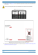
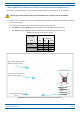
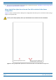
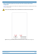
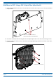
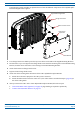
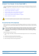
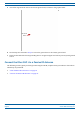
Table Of Contents
- Table of Contents
- Document Overview
- Era System Overview
- Fiber CAP L Overview
- Plan and Prepare for a Fiber CAP L Installation
- Maximum Number of Fiber CAP Ls Supported in an Era System
- Cascade Rules for Fiber CAP Ls
- Cat6A Cable Requirements for Ethernet Devices
- Safely Working with Era Hardware
- Determine the Power Consumption of the CAP L
- Determine the CAP L Installation Site
- Recommended Tools and Material
- Unpack and Inspect the CAP L and Optional Accessories
- Obtain the Required Materials
- Mount the Fiber CAP L
- General Mounting Cautions
- Mounting a CAP L with a Flat Mounting Bracket Kit
- Mounting Two CAP Ls with a Dual Mounting Kit
- Mounting a CAP L with an AC/DC Power Supply Kit
- Wiring the AC/DC Power Supply Kit.
- Mounting a CAP L with a Hybrid Fiber Splice Box Kit
- Prepare for CAP L Hybrid Fiber Splice Box Kit Installation
- Assembling and Wiring the Hybrid Fiber Splice Box
- Wire the Hybrid Fiber Splice Box
- Wire a Hybrid Fiber Splice Box for 4-Wire Power with Limited Power Source
- Wire a Hybrid Fiber Splice Box for 2-Wire Power without Limited Power Source
- Wire a Hybrid Fiber Splice Box to Cascade Two CAP Ls with the 2-Wire Power Configuration
- Wire a Hybrid Fiber Splice Box to Cascade Two CAP Ls with the 4-Wire Power Configuration
- Wall Mount a CAP L Using a CAP L Hybrid Fiber Splice Box Kit
- Ceiling Mount a CAP L
- Connect the Cables to the Fiber CAP L
- Powering on a Fiber CAP L
- CAP L Maintenance
- Contacting CommScope

M0201ANC_uc CommScope Era
™
Fiber Low Power Carrier Access Point Installation Guide
© June 2019 CommScope, Inc. Page 53
Mount the Fiber CAP L
The following graphic provides an exploded view of how the different components of the Hybrid Splice
Box Mounting Kit come together.
Angled Mounng Bracket
Flange-head screw
M6-1.0 x14mm screw
Hybrid Fiber
Splice Box
Wall Bracket
4 Put a flange-head screw halfway into the top screw holes on the side of the Angled Mounting Brackets.
5 Lift the CAP L
so you can align the two flange-head screws with the mounting slots on the Wall Mounting
Bracket, and then lower the CAP L so that it hangs on the Wall Mounting Bracket.
6 At
tach the bottom two flange-head screws.
7 Tighten all four flange-head sc
rews.
8 Attach the cables running from the bottom of t
he CAP L Hybrid Fiber Splice Box Kit.
a Attach the Local Power Jumper to the CAP L
power connector.
b Attach the Fiber Patch Cord to the CAP L Port 1; the other end was attached in Step 4c (page 44) to
on
e of the cable glands.
9 After you mount the
CAP L with
a CAP L Hybrid Fiber Splice Box Kit, follow the steps in
• "Ground the Fiber CAP L (Optional)” on page 55 (if grounding is required or preferred)
• "Connect the Passive RF Antenna” on page 59.