
Installation Guide
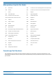
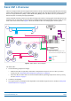
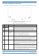
Table Of Contents
- Table of Contents
- Document Overview
- Era System Overview
- Fiber CAP L Overview
- Plan and Prepare for a Fiber CAP L Installation
- Maximum Number of Fiber CAP Ls Supported in an Era System
- Cascade Rules for Fiber CAP Ls
- Cat6A Cable Requirements for Ethernet Devices
- Safely Working with Era Hardware
- Determine the Power Consumption of the CAP L
- Determine the CAP L Installation Site
- Recommended Tools and Material
- Unpack and Inspect the CAP L and Optional Accessories
- Obtain the Required Materials
- Mount the Fiber CAP L
- General Mounting Cautions
- Mounting a CAP L with a Flat Mounting Bracket Kit
- Mounting Two CAP Ls with a Dual Mounting Kit
- Mounting a CAP L with an AC/DC Power Supply Kit
- Wiring the AC/DC Power Supply Kit.
- Mounting a CAP L with a Hybrid Fiber Splice Box Kit
- Prepare for CAP L Hybrid Fiber Splice Box Kit Installation
- Assembling and Wiring the Hybrid Fiber Splice Box
- Wire the Hybrid Fiber Splice Box
- Wire a Hybrid Fiber Splice Box for 4-Wire Power with Limited Power Source
- Wire a Hybrid Fiber Splice Box for 2-Wire Power without Limited Power Source
- Wire a Hybrid Fiber Splice Box to Cascade Two CAP Ls with the 2-Wire Power Configuration
- Wire a Hybrid Fiber Splice Box to Cascade Two CAP Ls with the 4-Wire Power Configuration
- Wall Mount a CAP L Using a CAP L Hybrid Fiber Splice Box Kit
- Ceiling Mount a CAP L
- Connect the Cables to the Fiber CAP L
- Powering on a Fiber CAP L
- CAP L Maintenance
- Contacting CommScope

M0201ANC_uc CommScope Era
™
Fiber Low Power Carrier Access Point Installation Guide
© June 2019 CommScope, Inc. Page 1
DOCUMENT OVERVIEW
There are two variants available for Low Power Carrier Access Points (CAP L): one variant has an optical fiber
interface (Fiber CAP L), and the other has a copper interface (Copper CAP L). This installation guide provides
a product overview and installation instructions fo
r the Fiber CAP L. (For information on the Copper CAP L,
refer to
the CommScopeEra™CopperLowPowerCarrierAccessPointInstallationGuide; see "A c c e ss i n g
Era/ION-E Series User Documentation” on
page 66). Table 1 lists the CAP L models that this installation guide
supports.
Table 1. Supported CAP L Models
Part Number
1
Model Name
7770203-000x CAP L 17E/17E/23/23
7770209-000x CAP L 18/21/26/26
7770356-000x CAP L 17E/17E/19/19
7776595-000x CAP L 9/18/18/21
7776596-000x CAP L 7/80-85/17E/19
7776597-000x CAP L 17E/19/23/25TDD
7776598-000x CAP L 9/18/21/26
7776641-000x CAP L 8/9/18/21
7776643-000x CAP L 8/18/21/26
1 The “-000x” suffix provides information as to
wh
eth
er the CA P L has a Fiber or Copper
interface, and the power and Fan Kit options.
Contact your local sales representative for
further information.
For information on how to find the minimum software requirements for Era hardware, refer to "Hardware
to Software Mapping Information” on page 65.
Document Revision History
This is the third release of the CommScopeEra™FiberLowPowerCarrierAccessPointInstallationGuide.