
Installation Guide

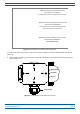
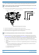


Table Of Contents
- Table of Contents
- Document Overview
- Era System Overview
- Fiber CAP L Overview
- Plan and Prepare for a Fiber CAP L Installation
- Maximum Number of Fiber CAP Ls Supported in an Era System
- Cascade Rules for Fiber CAP Ls
- Cat6A Cable Requirements for Ethernet Devices
- Safely Working with Era Hardware
- Determine the Power Consumption of the CAP L
- Determine the CAP L Installation Site
- Recommended Tools and Material
- Unpack and Inspect the CAP L and Optional Accessories
- Obtain the Required Materials
- Mount the Fiber CAP L
- General Mounting Cautions
- Mounting a CAP L with a Flat Mounting Bracket Kit
- Mounting Two CAP Ls with a Dual Mounting Kit
- Mounting a CAP L with an AC/DC Power Supply Kit
- Wiring the AC/DC Power Supply Kit.
- Mounting a CAP L with a Hybrid Fiber Splice Box Kit
- Prepare for CAP L Hybrid Fiber Splice Box Kit Installation
- Assembling and Wiring the Hybrid Fiber Splice Box
- Wire the Hybrid Fiber Splice Box
- Wire a Hybrid Fiber Splice Box for 4-Wire Power with Limited Power Source
- Wire a Hybrid Fiber Splice Box for 2-Wire Power without Limited Power Source
- Wire a Hybrid Fiber Splice Box to Cascade Two CAP Ls with the 2-Wire Power Configuration
- Wire a Hybrid Fiber Splice Box to Cascade Two CAP Ls with the 4-Wire Power Configuration
- Wall Mount a CAP L Using a CAP L Hybrid Fiber Splice Box Kit
- Ceiling Mount a CAP L
- Connect the Cables to the Fiber CAP L
- Powering on a Fiber CAP L
- CAP L Maintenance
- Contacting CommScope

240W Local AC Power Supply Kit, No AC Cord
(CommScope PN 7775087-xx)
AC Input power cord to be supplied by the installer.
240W Local AC Power Supply Kit with AC Input Cord
(CommScope PN 7809798-xx)
3m AC input cord is connected internally to PSU
but unterminated at customer end.
240W Local AC Power Supply Kit for Plenum Space
(CommScope PN 7809823-xx)
Not for outdoor use!
M0201ANC_uc CommScope Era
™
Fiber Low Power Carrier Access Point Installation Guide
© June 2019 CommScope, Inc. Page 39
Mount the Fiber CAP L
Figure 14. CommScope Local AC/DC Power Supply Kits
To insert and connect the AC input cord for kit number 7775087-xx and kit num
ber 7809823-xx, do the
following:
1 Remove the four Phillip
s head screws from the left junction box cover of the kit and then remove the
junction box cover.
Cable Gland
ACN BLUE
ACL BROWN
GREEN/YELLOW
Figure 15. AC/DC Supply Junction Box Cover Screws