
Installation Guide

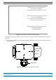
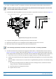


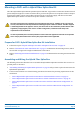


Table Of Contents
- Table of Contents
- Document Overview
- Era System Overview
- Fiber CAP L Overview
- Plan and Prepare for a Fiber CAP L Installation
- Maximum Number of Fiber CAP Ls Supported in an Era System
- Cascade Rules for Fiber CAP Ls
- Cat6A Cable Requirements for Ethernet Devices
- Safely Working with Era Hardware
- Determine the Power Consumption of the CAP L
- Determine the CAP L Installation Site
- Recommended Tools and Material
- Unpack and Inspect the CAP L and Optional Accessories
- Obtain the Required Materials
- Mount the Fiber CAP L
- General Mounting Cautions
- Mounting a CAP L with a Flat Mounting Bracket Kit
- Mounting Two CAP Ls with a Dual Mounting Kit
- Mounting a CAP L with an AC/DC Power Supply Kit
- Wiring the AC/DC Power Supply Kit.
- Mounting a CAP L with a Hybrid Fiber Splice Box Kit
- Prepare for CAP L Hybrid Fiber Splice Box Kit Installation
- Assembling and Wiring the Hybrid Fiber Splice Box
- Wire the Hybrid Fiber Splice Box
- Wire a Hybrid Fiber Splice Box for 4-Wire Power with Limited Power Source
- Wire a Hybrid Fiber Splice Box for 2-Wire Power without Limited Power Source
- Wire a Hybrid Fiber Splice Box to Cascade Two CAP Ls with the 2-Wire Power Configuration
- Wire a Hybrid Fiber Splice Box to Cascade Two CAP Ls with the 4-Wire Power Configuration
- Wall Mount a CAP L Using a CAP L Hybrid Fiber Splice Box Kit
- Ceiling Mount a CAP L
- Connect the Cables to the Fiber CAP L
- Powering on a Fiber CAP L
- CAP L Maintenance
- Contacting CommScope

CommScope Era
™
Fiber Low Power Carrier Access Point Installation Guide M0201ANC_uc
Page 38 © June 2019 CommScope, Inc.
Mount the Fiber CAP L
Mounting a CAP L with an AC/DC Power Supply Kit
An AC/DC Power Supply Kit provides a 48V External Power Supply that converts local AC power to DC power
for the CAP L. An AC/DC Power Supply Kit can be used for a Fiber or Copper In
terface when an AC power
source is located near the CAP L.
Figure 13. CAP L with AC/DC Power Supply Kit
Do the following to mount a CAP L using an AC/DC Power Supply Kit.
1 Obtain the AC/DC Power Supply Kit that is appropriate for this installation. Figu
re 14 on page 39 lists the
three AC/DC Power Supply Kit part numbers; se
e also "CommScope Part Numbers” on page 3.
2 Refer to and observe all cautions listed in "Gener
al Mounting Cautions” on page 24.
3 Refer to "Determine the CAP L Installation Site” on page 17 to determine the mounting location, which
must be able to support the weight
and dimensions of the CAP
L.
4 Refer to "Mo
unting Orientation for Wall Mounts” on page 29 to determine the mounting orientation of the
CAP L.
5 F
ollow the steps in "Unpack and Inspect the CAP L
and Optional Accessories” on page 23.
Wiring the AC/DC Power Supply Kit.
The CommScope Local AC Power Supply Kits are available in three configurations as shown in "CommScope
Local AC/DC Power Supply Kits” on page 39. The installer must supply and install the AC input power cord fo
r
kit number 7775087-xx and kit number 7809823-xx. The AC input pow
er cord for kit number 7809798-xx is
connected internally but is unterminated at the customer end.