
Installation Guide
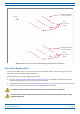
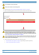

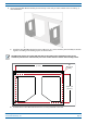


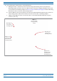
Table Of Contents
- Table of Contents
- Document Overview
- Era System Overview
- Fiber CAP L Overview
- Plan and Prepare for a Fiber CAP L Installation
- Maximum Number of Fiber CAP Ls Supported in an Era System
- Cascade Rules for Fiber CAP Ls
- Cat6A Cable Requirements for Ethernet Devices
- Safely Working with Era Hardware
- Determine the Power Consumption of the CAP L
- Determine the CAP L Installation Site
- Recommended Tools and Material
- Unpack and Inspect the CAP L and Optional Accessories
- Obtain the Required Materials
- Mount the Fiber CAP L
- General Mounting Cautions
- Mounting a CAP L with a Flat Mounting Bracket Kit
- Mounting Two CAP Ls with a Dual Mounting Kit
- Mounting a CAP L with an AC/DC Power Supply Kit
- Wiring the AC/DC Power Supply Kit.
- Mounting a CAP L with a Hybrid Fiber Splice Box Kit
- Prepare for CAP L Hybrid Fiber Splice Box Kit Installation
- Assembling and Wiring the Hybrid Fiber Splice Box
- Wire the Hybrid Fiber Splice Box
- Wire a Hybrid Fiber Splice Box for 4-Wire Power with Limited Power Source
- Wire a Hybrid Fiber Splice Box for 2-Wire Power without Limited Power Source
- Wire a Hybrid Fiber Splice Box to Cascade Two CAP Ls with the 2-Wire Power Configuration
- Wire a Hybrid Fiber Splice Box to Cascade Two CAP Ls with the 4-Wire Power Configuration
- Wall Mount a CAP L Using a CAP L Hybrid Fiber Splice Box Kit
- Ceiling Mount a CAP L
- Connect the Cables to the Fiber CAP L
- Powering on a Fiber CAP L
- CAP L Maintenance
- Contacting CommScope

CommScope Era
™
Fiber Low Power Carrier Access Point Installation Guide M0201ANC_uc
Page 36 © June 2019 CommScope, Inc.
Mount the Fiber CAP L
9 Do the following to mount CAP L-1 in the Wall Bracket.
a Holding th
e CAP L-1 with the front of the chassis facing the mounting surface, lift it above the
Mounting Bracket attached to the wall, and then lower it into place, aligning the M8x16 screws that
you attached to the Mounting Adapters in Step 7 on page 35 and Step 8 on page 35 with the Mounting
Bracket slots that are closest to the mounting surface.
b Insert an M8x16 screw into the bottom screw hole of the Dual Wall Mount Bracket that is closest to
the mo
unting surface and into the bottom screw hole on each CAP L-1 Mounting Adapter.
c Tighten all four M8x16 screws
to secure the CAP L-1 to the Dual Wall Mount Bracket; torque to
13.5 N-m (120 in-lb).
M8x16 screw
in boom screw
hole closest to
mounng surface
Mounng slot
closest to the
mounng surface
CAP L-1
Front of chassis
facing mounng
surface
M8x16 screw
in boom screw
hole closest to
mounng surface
Mounng slot
closest to the
mounng surface