
Installation Guide
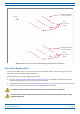
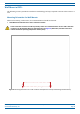

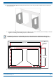


Table Of Contents
- Table of Contents
- Document Overview
- Era System Overview
- Fiber CAP L Overview
- Plan and Prepare for a Fiber CAP L Installation
- Maximum Number of Fiber CAP Ls Supported in an Era System
- Cascade Rules for Fiber CAP Ls
- Cat6A Cable Requirements for Ethernet Devices
- Safely Working with Era Hardware
- Determine the Power Consumption of the CAP L
- Determine the CAP L Installation Site
- Recommended Tools and Material
- Unpack and Inspect the CAP L and Optional Accessories
- Obtain the Required Materials
- Mount the Fiber CAP L
- General Mounting Cautions
- Mounting a CAP L with a Flat Mounting Bracket Kit
- Mounting Two CAP Ls with a Dual Mounting Kit
- Mounting a CAP L with an AC/DC Power Supply Kit
- Wiring the AC/DC Power Supply Kit.
- Mounting a CAP L with a Hybrid Fiber Splice Box Kit
- Prepare for CAP L Hybrid Fiber Splice Box Kit Installation
- Assembling and Wiring the Hybrid Fiber Splice Box
- Wire the Hybrid Fiber Splice Box
- Wire a Hybrid Fiber Splice Box for 4-Wire Power with Limited Power Source
- Wire a Hybrid Fiber Splice Box for 2-Wire Power without Limited Power Source
- Wire a Hybrid Fiber Splice Box to Cascade Two CAP Ls with the 2-Wire Power Configuration
- Wire a Hybrid Fiber Splice Box to Cascade Two CAP Ls with the 4-Wire Power Configuration
- Wall Mount a CAP L Using a CAP L Hybrid Fiber Splice Box Kit
- Ceiling Mount a CAP L
- Connect the Cables to the Fiber CAP L
- Powering on a Fiber CAP L
- CAP L Maintenance
- Contacting CommScope

CommScope Era
™
Fiber Low Power Carrier Access Point Installation Guide M0201ANC_uc
Page 30 © June 2019 CommScope, Inc.
Mount the Fiber CAP L
• WallMountOrientationforaCAPLwithaFanKit—To allow for optimal access to the CAP L cables, it
is recommended that a Fiber CAP L with the Fan Kit option be mounted with the ANT ports are pointing
to the left; se
e Figure 10.
ANT connectors
poinng to the le
Figure 10. Mounting Orientation for a CAP L with the Optional Fan Kit (Flat Mounting Bracket Shown)
Mounting requirements for flat surfaces are described in "Flat-Surface Mount a CAP L” on page 27.
Ceiling-mount requirements are described in "Ceiling Mount a CAP L with a Fan Kit” on page 54.
Wall Mount a CAP L Using a Flat Mounting Bracket Kit
1 Use "Plan and Prepare for a Fiber CAP L Installation” on page 10 to identify the installation site and
installation requirements, and to prepare for the installation.
2 Refer to and observe all cautions listed in "Gener
al Mounting Cautions” on page 24.
3 Follow the steps in "Attach the Flat Mounting Brack
et Kit to the CAP L” on page 26.
4 Refer to "Mo
unting Orientation for Wall Mounts” on page 29 to determine the mounting orientation of the
Fiber CAP L.