
Installation Guide
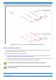
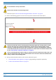
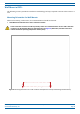

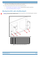
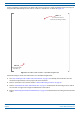
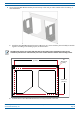


Table Of Contents
- Table of Contents
- Document Overview
- Era System Overview
- Fiber CAP L Overview
- Plan and Prepare for a Fiber CAP L Installation
- Maximum Number of Fiber CAP Ls Supported in an Era System
- Cascade Rules for Fiber CAP Ls
- Cat6A Cable Requirements for Ethernet Devices
- Safely Working with Era Hardware
- Determine the Power Consumption of the CAP L
- Determine the CAP L Installation Site
- Recommended Tools and Material
- Unpack and Inspect the CAP L and Optional Accessories
- Obtain the Required Materials
- Mount the Fiber CAP L
- General Mounting Cautions
- Mounting a CAP L with a Flat Mounting Bracket Kit
- Mounting Two CAP Ls with a Dual Mounting Kit
- Mounting a CAP L with an AC/DC Power Supply Kit
- Wiring the AC/DC Power Supply Kit.
- Mounting a CAP L with a Hybrid Fiber Splice Box Kit
- Prepare for CAP L Hybrid Fiber Splice Box Kit Installation
- Assembling and Wiring the Hybrid Fiber Splice Box
- Wire the Hybrid Fiber Splice Box
- Wire a Hybrid Fiber Splice Box for 4-Wire Power with Limited Power Source
- Wire a Hybrid Fiber Splice Box for 2-Wire Power without Limited Power Source
- Wire a Hybrid Fiber Splice Box to Cascade Two CAP Ls with the 2-Wire Power Configuration
- Wire a Hybrid Fiber Splice Box to Cascade Two CAP Ls with the 4-Wire Power Configuration
- Wall Mount a CAP L Using a CAP L Hybrid Fiber Splice Box Kit
- Ceiling Mount a CAP L
- Connect the Cables to the Fiber CAP L
- Powering on a Fiber CAP L
- CAP L Maintenance
- Contacting CommScope

CommScope Era
™
Fiber Low Power Carrier Access Point Installation Guide M0201ANC_uc
Page 28 © June 2019 CommScope, Inc.
Mount the Fiber CAP L
3 Follow the steps in "Attach the Flat Mounting Bracket Kit to the CAP L” on page 26.
4 Refer to the following graphic to see the correct way to flat-surface m
ount a Fiber CAP L.
Fins facing up
Flat Surface Mount
Flat-Mounng Bracket
opon secures the
CAP L to the flat
surface.
Fins Facing down
Ceiling Mount with the CAP L Fins facing down – Fan Kit is recommended. See note below!
Always mount the CAP L with its mounting option facing down against the mounting surface, and the
enclosure fins facing up for optimal cooling efficiency, as shown in the preceding graphic. Cooling
efficiency is reduced when the enclosure fins are facing down; a fan kit is recommended for maximum
service life when the CAP L is mounted in this orientation. For further details on installation without a fan
kit, see "Extended CAP L Temperature Operation” on page 22
.
If you are mounting the CAP L above a ceiling, its antennas must protrude below the ceiling. That is, the
CAP L will be above the ceiling, but any connected WiFi units or IP cameras will be mounted below the
ceiling, as shown in the preceding graphic.
5 After you mount the Fiber CAP L on a flat surface, follow the steps in
• "Ground the Fiber CAP L (Optional)” on page 55 (if grounding is required or preferred)
• "Connect the Passive RF Antenna” on page 59.
Do not stack CAP Ls on top of each other.
Always secure the CAP L to the mounting surface.