
Installation Guide
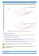
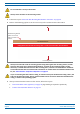
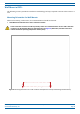

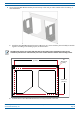


Table Of Contents
- Table of Contents
- Document Overview
- Era System Overview
- Fiber CAP L Overview
- Plan and Prepare for a Fiber CAP L Installation
- Maximum Number of Fiber CAP Ls Supported in an Era System
- Cascade Rules for Fiber CAP Ls
- Cat6A Cable Requirements for Ethernet Devices
- Safely Working with Era Hardware
- Determine the Power Consumption of the CAP L
- Determine the CAP L Installation Site
- Recommended Tools and Material
- Unpack and Inspect the CAP L and Optional Accessories
- Obtain the Required Materials
- Mount the Fiber CAP L
- General Mounting Cautions
- Mounting a CAP L with a Flat Mounting Bracket Kit
- Mounting Two CAP Ls with a Dual Mounting Kit
- Mounting a CAP L with an AC/DC Power Supply Kit
- Wiring the AC/DC Power Supply Kit.
- Mounting a CAP L with a Hybrid Fiber Splice Box Kit
- Prepare for CAP L Hybrid Fiber Splice Box Kit Installation
- Assembling and Wiring the Hybrid Fiber Splice Box
- Wire the Hybrid Fiber Splice Box
- Wire a Hybrid Fiber Splice Box for 4-Wire Power with Limited Power Source
- Wire a Hybrid Fiber Splice Box for 2-Wire Power without Limited Power Source
- Wire a Hybrid Fiber Splice Box to Cascade Two CAP Ls with the 2-Wire Power Configuration
- Wire a Hybrid Fiber Splice Box to Cascade Two CAP Ls with the 4-Wire Power Configuration
- Wall Mount a CAP L Using a CAP L Hybrid Fiber Splice Box Kit
- Ceiling Mount a CAP L
- Connect the Cables to the Fiber CAP L
- Powering on a Fiber CAP L
- CAP L Maintenance
- Contacting CommScope

One Mounng bracket
in vercal posion
Three
M6-1.0 x 14mm
screws
One Mounng bracket
in vercal posion
Three
M6-1.0 x 14mm
screws
Fan Kit
M0201ANC_uc CommScope Era
™
Fiber Low Power Carrier Access Point Installation Guide
© June 2019 CommScope, Inc. Page 27
Mount the Fiber CAP L
Figure 8. Fiber AP L with a Fan Kit and Flat Mounting Bracket Kit (PN 7774353-xx)
Flat-Surface Mount a CAP L
You can place a Fiber CAP L on a flat surface, such as a shelf, desk, cabinet, above a ceiling, or any other
horizontal surface that allows stable placement.
Do the following to flat-surface mount a Fiber CAP L:
1 Use "Plan and Prepare for a Fiber CAP L Installation” on page 10 to identify the installation site and
installation requirements, and to prepare for
this
installation.
2 In addition to the cautions listed in
"General Mounting Cautions” on page 24, observe the rules that are
specific to a flat-surface mounts listed below and els
ewhere in this section.
To maintain proper ventilation, keep at least 76 mm (3-inch) clearance around the CAP L.
If a CAP L without a Fan Kit is flat-surface mounted, the minimum clearance above the CAP L is 203.2
millimeters (8 inches).