
Installation Guide
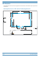
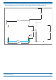
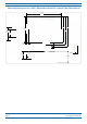

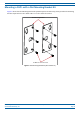
Table Of Contents
- Table of Contents
- Document Overview
- Era System Overview
- Fiber CAP L Overview
- Plan and Prepare for a Fiber CAP L Installation
- Maximum Number of Fiber CAP Ls Supported in an Era System
- Cascade Rules for Fiber CAP Ls
- Cat6A Cable Requirements for Ethernet Devices
- Safely Working with Era Hardware
- Determine the Power Consumption of the CAP L
- Determine the CAP L Installation Site
- Recommended Tools and Material
- Unpack and Inspect the CAP L and Optional Accessories
- Obtain the Required Materials
- Mount the Fiber CAP L
- General Mounting Cautions
- Mounting a CAP L with a Flat Mounting Bracket Kit
- Mounting Two CAP Ls with a Dual Mounting Kit
- Mounting a CAP L with an AC/DC Power Supply Kit
- Wiring the AC/DC Power Supply Kit.
- Mounting a CAP L with a Hybrid Fiber Splice Box Kit
- Prepare for CAP L Hybrid Fiber Splice Box Kit Installation
- Assembling and Wiring the Hybrid Fiber Splice Box
- Wire the Hybrid Fiber Splice Box
- Wire a Hybrid Fiber Splice Box for 4-Wire Power with Limited Power Source
- Wire a Hybrid Fiber Splice Box for 2-Wire Power without Limited Power Source
- Wire a Hybrid Fiber Splice Box to Cascade Two CAP Ls with the 2-Wire Power Configuration
- Wire a Hybrid Fiber Splice Box to Cascade Two CAP Ls with the 4-Wire Power Configuration
- Wall Mount a CAP L Using a CAP L Hybrid Fiber Splice Box Kit
- Ceiling Mount a CAP L
- Connect the Cables to the Fiber CAP L
- Powering on a Fiber CAP L
- CAP L Maintenance
- Contacting CommScope

CommScope Era
™
Fiber Low Power Carrier Access Point Installation Guide M0201ANC_uc
Page 24 © June 2019 CommScope, Inc.
Mount the Fiber CAP L
MOUNT THE FIBER CAP L
A Fiber CAP L is suitable for indoor and outdoor installations as follows:
• Indoors—All vers
ions of the Fiber CAP L can be installed indoors.
• Outdoors—Only Fiber CAP Ls with the optional Fan Kit can be
installed outdoors.
Mounting instructions are divided into the sections listed below. Follo
w the mounting instructions that are
applicable to this installation:
• "Flat-Surface Mount a CAP L” on page 27
• "Wall Mount a CAP L” on page 29
– "Mounting Orientation for Wall Mounts” on page 29
– "Wall Mount a CAP L Using a Flat Mounting Br
ack
et Kit” on page 30
– "Mounting Two CAP Ls with a Dual Mounting Kit” on page 31
– "Mounting a CAP L with an AC/DC Power Supply Kit” on page 38
– "Mounting a CAP L with a Hybrid Fiber Splice Box Kit
” on page 43
• "Ceiling Mount a CAP L” on page 54
– "Ceiling Mount a CAP L without a Fan Kit” on page 54
– "Ceiling Mount a CAP L with a Fan Kit” on page 54.
General Mounting Cautions
The following cautions apply to all Fiber CAP L installations; there may be other mounting cautions applicable
to a specific mounting option, which will be defined in the applicable mounting procedure.
Attach all CAP Ls securely to a stationary object as described in this installation guide.
To maintain proper ventilation, keep at least 76 mm (3-inch) clearance around the CAP L.
The installation site must be able to bear the weight of the CAP L; see Table 8 on page 21.