
Installation Guide
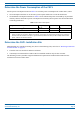

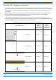
Table Of Contents
- Table of Contents
- Document Overview
- Era System Overview
- Fiber CAP L Overview
- Plan and Prepare for a Fiber CAP L Installation
- Maximum Number of Fiber CAP Ls Supported in an Era System
- Cascade Rules for Fiber CAP Ls
- Cat6A Cable Requirements for Ethernet Devices
- Safely Working with Era Hardware
- Determine the Power Consumption of the CAP L
- Determine the CAP L Installation Site
- Recommended Tools and Material
- Unpack and Inspect the CAP L and Optional Accessories
- Obtain the Required Materials
- Mount the Fiber CAP L
- General Mounting Cautions
- Mounting a CAP L with a Flat Mounting Bracket Kit
- Mounting Two CAP Ls with a Dual Mounting Kit
- Mounting a CAP L with an AC/DC Power Supply Kit
- Wiring the AC/DC Power Supply Kit.
- Mounting a CAP L with a Hybrid Fiber Splice Box Kit
- Prepare for CAP L Hybrid Fiber Splice Box Kit Installation
- Assembling and Wiring the Hybrid Fiber Splice Box
- Wire the Hybrid Fiber Splice Box
- Wire a Hybrid Fiber Splice Box for 4-Wire Power with Limited Power Source
- Wire a Hybrid Fiber Splice Box for 2-Wire Power without Limited Power Source
- Wire a Hybrid Fiber Splice Box to Cascade Two CAP Ls with the 2-Wire Power Configuration
- Wire a Hybrid Fiber Splice Box to Cascade Two CAP Ls with the 4-Wire Power Configuration
- Wall Mount a CAP L Using a CAP L Hybrid Fiber Splice Box Kit
- Ceiling Mount a CAP L
- Connect the Cables to the Fiber CAP L
- Powering on a Fiber CAP L
- CAP L Maintenance
- Contacting CommScope

CommScope Era
™
Fiber Low Power Carrier Access Point Installation Guide M0201ANC_uc
Page 22 © June 2019 CommScope, Inc.
Plan and Prepare for a Fiber CAP L Installation
Extended CAP L Temperature Operation
The passively cooled CAP L is rated for a maximum temperature of 40°C (104°F). This temperature range
guarantees maximum service life under worst-case load conditions. If necessary, however, it can be operated
safely at higher temperatures without exceeding the maximum temperatures of the internal electronic
components.
Various components in the CAP L have temperature sensors and will alarm once they get within about 5
degrees o
f their maximum allowed temperature. The CAP L will disable itself if any of the internal
temperatures
exceeds the maximum allowed temperature.
The maximum ambient temperature of the CAP L is dependent on the mounting configuration, as th
e
mounting
configuration affects the ability of the CAP L to dissipate heat. The various mounting configurations
and resulting temp
erature ranges of operation are detailed in Table 9.
Table 9. CAP L Extended Temperature Operation by Mounting Orientation
Mounting Orientation
Recommended
Maximum
Ambient
Temperature
(Alarm Threshold)
Absolute
Maximum
Ambient
Temperature
(S
hutdown Temp.)
Vertical Mount 60 °C (140°F) 65 °C (149°F)
Dual Vertical Mount 58 °C (136.4°F) 63 °C (145.4°F)
Flat Surface Mount
Fins facing up
Flat Surface Mount 54 °C (129.2°F) 59 °C (138.2°F)
Fins Facing down
Ceiling Mount with Fins Down
Ceiling Mount 48 °C (118.4°F) 53 °C (127.4°F)