
Installation Guide
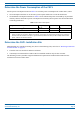
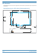
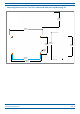
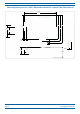

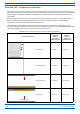
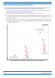
Table Of Contents
- Table of Contents
- Document Overview
- Era System Overview
- Fiber CAP L Overview
- Plan and Prepare for a Fiber CAP L Installation
- Maximum Number of Fiber CAP Ls Supported in an Era System
- Cascade Rules for Fiber CAP Ls
- Cat6A Cable Requirements for Ethernet Devices
- Safely Working with Era Hardware
- Determine the Power Consumption of the CAP L
- Determine the CAP L Installation Site
- Recommended Tools and Material
- Unpack and Inspect the CAP L and Optional Accessories
- Obtain the Required Materials
- Mount the Fiber CAP L
- General Mounting Cautions
- Mounting a CAP L with a Flat Mounting Bracket Kit
- Mounting Two CAP Ls with a Dual Mounting Kit
- Mounting a CAP L with an AC/DC Power Supply Kit
- Wiring the AC/DC Power Supply Kit.
- Mounting a CAP L with a Hybrid Fiber Splice Box Kit
- Prepare for CAP L Hybrid Fiber Splice Box Kit Installation
- Assembling and Wiring the Hybrid Fiber Splice Box
- Wire the Hybrid Fiber Splice Box
- Wire a Hybrid Fiber Splice Box for 4-Wire Power with Limited Power Source
- Wire a Hybrid Fiber Splice Box for 2-Wire Power without Limited Power Source
- Wire a Hybrid Fiber Splice Box to Cascade Two CAP Ls with the 2-Wire Power Configuration
- Wire a Hybrid Fiber Splice Box to Cascade Two CAP Ls with the 4-Wire Power Configuration
- Wall Mount a CAP L Using a CAP L Hybrid Fiber Splice Box Kit
- Ceiling Mount a CAP L
- Connect the Cables to the Fiber CAP L
- Powering on a Fiber CAP L
- CAP L Maintenance
- Contacting CommScope

M0201ANC_uc CommScope Era
™
Fiber Low Power Carrier Access Point Installation Guide
© June 2019 CommScope, Inc. Page 21
Plan and Prepare for a Fiber CAP L Installation
Mounting Dimensions for a CAP L Mounted with the AC/DC Power Supply Kit
120mm
[4.72"]
398mm
[15.669"]
31.5mm
[1.24"]
104.73mm
[4.12"]
158.42mm
[6.24"]
188mm
[7.4"]
2X
30mm
[1.18"]
24mm
[0.94"]
2X
468.12mm
[18.43"]
432.45mm
[17.03"]
398.3mm
[15.68"]
448mm
[17.64"]
373.89mm
[14.72"]
87.44mm
[3.44"]
CAP L Weights
Use the weights listed in Table 8 to determine a site that can bear the weight of the Fiber CAP L that is being
installed, where:
• The “Maximum Lift Weight” is the highest weight that must be lif
ted during installation. (An installer only
needs to lift CAP L components at one time, not the wholly configured CAP L.)
• The “Total Hanging Weight” is the weight of the CAP L
, including the weight of the Mounting Bracket and
Power Supply, minus the weight of the external cables and connectors, that the mounting site must be
able to support.
Table 8. Maximum CAP L Installation Weights*
CAP L configured with this kit …
Maximum Lift Weight Total Hanging Weight
No Fan Kit With Fan Kit No Fan Kit With Fan Kit
kg lbs. kg lbs. kg lbs. kg lbs.
Flat Mounting Bracket 10.8 23.8 11.3 25 10.8 23.8 11.3 25
Dual Mounting Bracket 10.9 24.1 N/A 23.4 51.6 N/A
AC/DC Power Supply Kit 10.7 23.6 11.2 24.7 13.2 29 13.7 30.2
CAP L Hybrid Fiber Splice Box Kit 10.7 23.6 11.2 24.7 12.2 26.9 12.7 28