
Installation Guide
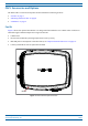
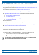

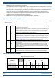
Table Of Contents
- Table of Contents
- Document Overview
- Era System Overview
- Fiber CAP L Overview
- Plan and Prepare for a Fiber CAP L Installation
- Maximum Number of Fiber CAP Ls Supported in an Era System
- Cascade Rules for Fiber CAP Ls
- Cat6A Cable Requirements for Ethernet Devices
- Safely Working with Era Hardware
- Determine the Power Consumption of the CAP L
- Determine the CAP L Installation Site
- Recommended Tools and Material
- Unpack and Inspect the CAP L and Optional Accessories
- Obtain the Required Materials
- Mount the Fiber CAP L
- General Mounting Cautions
- Mounting a CAP L with a Flat Mounting Bracket Kit
- Mounting Two CAP Ls with a Dual Mounting Kit
- Mounting a CAP L with an AC/DC Power Supply Kit
- Wiring the AC/DC Power Supply Kit.
- Mounting a CAP L with a Hybrid Fiber Splice Box Kit
- Prepare for CAP L Hybrid Fiber Splice Box Kit Installation
- Assembling and Wiring the Hybrid Fiber Splice Box
- Wire the Hybrid Fiber Splice Box
- Wire a Hybrid Fiber Splice Box for 4-Wire Power with Limited Power Source
- Wire a Hybrid Fiber Splice Box for 2-Wire Power without Limited Power Source
- Wire a Hybrid Fiber Splice Box to Cascade Two CAP Ls with the 2-Wire Power Configuration
- Wire a Hybrid Fiber Splice Box to Cascade Two CAP Ls with the 4-Wire Power Configuration
- Wall Mount a CAP L Using a CAP L Hybrid Fiber Splice Box Kit
- Ceiling Mount a CAP L
- Connect the Cables to the Fiber CAP L
- Powering on a Fiber CAP L
- CAP L Maintenance
- Contacting CommScope

M0201ANC_uc CommScope Era
™
Fiber Low Power Carrier Access Point Installation Guide
© June 2019 CommScope, Inc. Page 13
Plan and Prepare for a Fiber CAP L Installation
Property Damage Warnings
Keep operating instructions within easy reach and make them available to all users.
Only license holders for the respective frequency range are allowed to operate this unit.
Read and obey all the warning labels attached to the unit. Make sure that all warning labels are kept in a
legible condition. Replace any missing or damaged labels.
Make sure the unit's settings are correct for the intended use (refer to the manufacturer product
information) and regulatory requirements are met. Do not carry out any modifications or fit any spare
parts, which are not sold or recommended by the manufacturer.
General Installation Safety Requirements
Wet conditions increase the potential for receiving an electrical shock when installing or using electrically
powered equipment. To prevent electrical shock, never install or use electrical equipment in a wet
location or during a lightning storm.
This system is a RF Transmitter and continuously emits RF energy. Maintain a minimum clearance from
the antenna as specified in Table 6 while the system is operating. Whenever p
ossible, power down the
CAP
L before servicing the antenna.
Do not remove caps from any of the connectors until instructed to do so.
The CAP L is to be used only with CommScope (NEC Class 2) or Limited Power Source Era Subrack, or
equivalent.
Guard Against Damage from Electro-Static Discharge
Electro-Static Discharge (ESD) can damage electronic components. To prevent ESD damage, always wear
an ESD wrist strap when working with Era hardware components. Not all Era hardware requires
grounding. For those Era hardware components for which grounding is required, connect the ground wire
on the ESD wrist strap to an earth ground source before touching the Era component. Wear the wrist
strap the entire time that you work with the Era hardware.