
Installation Guide
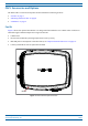
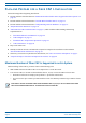
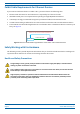

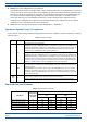
Table Of Contents
- Table of Contents
- Document Overview
- Era System Overview
- Fiber CAP L Overview
- Plan and Prepare for a Fiber CAP L Installation
- Maximum Number of Fiber CAP Ls Supported in an Era System
- Cascade Rules for Fiber CAP Ls
- Cat6A Cable Requirements for Ethernet Devices
- Safely Working with Era Hardware
- Determine the Power Consumption of the CAP L
- Determine the CAP L Installation Site
- Recommended Tools and Material
- Unpack and Inspect the CAP L and Optional Accessories
- Obtain the Required Materials
- Mount the Fiber CAP L
- General Mounting Cautions
- Mounting a CAP L with a Flat Mounting Bracket Kit
- Mounting Two CAP Ls with a Dual Mounting Kit
- Mounting a CAP L with an AC/DC Power Supply Kit
- Wiring the AC/DC Power Supply Kit.
- Mounting a CAP L with a Hybrid Fiber Splice Box Kit
- Prepare for CAP L Hybrid Fiber Splice Box Kit Installation
- Assembling and Wiring the Hybrid Fiber Splice Box
- Wire the Hybrid Fiber Splice Box
- Wire a Hybrid Fiber Splice Box for 4-Wire Power with Limited Power Source
- Wire a Hybrid Fiber Splice Box for 2-Wire Power without Limited Power Source
- Wire a Hybrid Fiber Splice Box to Cascade Two CAP Ls with the 2-Wire Power Configuration
- Wire a Hybrid Fiber Splice Box to Cascade Two CAP Ls with the 4-Wire Power Configuration
- Wall Mount a CAP L Using a CAP L Hybrid Fiber Splice Box Kit
- Ceiling Mount a CAP L
- Connect the Cables to the Fiber CAP L
- Powering on a Fiber CAP L
- CAP L Maintenance
- Contacting CommScope

CommScope Era
™
Fiber Low Power Carrier Access Point Installation Guide M0201ANC_uc
Page 12 © June 2019 CommScope, Inc.
Plan and Prepare for a Fiber CAP L Installation
Cat6A Cable Requirements for Ethernet Devices
If you connect an Ethernet device to a Fiber CAP L, you must observe the following rules.
• Plenum rated cable must be used whenever it is required by local electrical
codes.
• Shielded twisted pair is not required unless operating in a high RF
I/EMI environment.
• CommScope strongly recommends using fa
ctory terminated and tested Cat6A Patch Cord.
• 24 AWG Cat6A cabling is sufficient for the cable run between the
Fiber CAP L and the Ethernet device.
• The maximum attached cable length from Port A on the Fiber CAP L
to the Ethernet device is 3 meters (9.8
feet); see Figure 5.
From a Fiber CAP L to an Ethernet device,
Cat6A cannot exceed 3 meters (9.8 feet)
24 AWG Cat6A Cable
Fiber CAP L
Ethernet
Device
Figure 5. Maximum Cat6A Cable Length between a Fiber CAP L and an Ethernet Device
Safely Working with Era Hardware
The following sections provide important information that you should read and know before working with
any Era hardware. Observe all cautions and warnings listed in this section.
Health and Safety Precautions
A high leakage current ground (earth) connection to the Power Supply Unit (PSU) is essential before
making any other connections to the PSU.
Laser radiation. Risk of eye injury in operation. Do not stare into the laser beam; do not view the laser
beam directly or with optical instruments.
High frequency radiation in operation. Risk of health hazards associated with radiation from the
antenna(s) connected to the unit. Implement prevention measures to avoid the possibility of close
proximity to the antenna(s) while in operation.