
Installation Guide
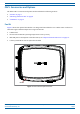
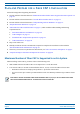

Table Of Contents
- Table of Contents
- Document Overview
- Era System Overview
- Fiber CAP L Overview
- Plan and Prepare for a Fiber CAP L Installation
- Maximum Number of Fiber CAP Ls Supported in an Era System
- Cascade Rules for Fiber CAP Ls
- Cat6A Cable Requirements for Ethernet Devices
- Safely Working with Era Hardware
- Determine the Power Consumption of the CAP L
- Determine the CAP L Installation Site
- Recommended Tools and Material
- Unpack and Inspect the CAP L and Optional Accessories
- Obtain the Required Materials
- Mount the Fiber CAP L
- General Mounting Cautions
- Mounting a CAP L with a Flat Mounting Bracket Kit
- Mounting Two CAP Ls with a Dual Mounting Kit
- Mounting a CAP L with an AC/DC Power Supply Kit
- Wiring the AC/DC Power Supply Kit.
- Mounting a CAP L with a Hybrid Fiber Splice Box Kit
- Prepare for CAP L Hybrid Fiber Splice Box Kit Installation
- Assembling and Wiring the Hybrid Fiber Splice Box
- Wire the Hybrid Fiber Splice Box
- Wire a Hybrid Fiber Splice Box for 4-Wire Power with Limited Power Source
- Wire a Hybrid Fiber Splice Box for 2-Wire Power without Limited Power Source
- Wire a Hybrid Fiber Splice Box to Cascade Two CAP Ls with the 2-Wire Power Configuration
- Wire a Hybrid Fiber Splice Box to Cascade Two CAP Ls with the 4-Wire Power Configuration
- Wall Mount a CAP L Using a CAP L Hybrid Fiber Splice Box Kit
- Ceiling Mount a CAP L
- Connect the Cables to the Fiber CAP L
- Powering on a Fiber CAP L
- CAP L Maintenance
- Contacting CommScope

M0201ANC_uc CommScope Era
™
Fiber Low Power Carrier Access Point Installation Guide
© June 2019 CommScope, Inc. Page 11
Plan and Prepare for a Fiber CAP L Installation
Cascade Rules for Fiber CAP Ls
When cascading a Secondary Fiber CAP L or an external Ethernet device such as WiFi or an IP camera, you
must observe the following rules.
• I
n a cascade, the CAP L connected directly to the Classic CAN or TEN is the Primary Fiber CAP L, and the
CAP L that connects to the Primary Fiber CAP L is the Secondary Fiber CAP L.
• The cascaded unit must use the same transport type—you
cannot cascade a Copper CAP L to a Fiber
CAP L.
• The
total 320 MHz RF bandwidth is shared between the two cascaded units, but can be shared unevenly;
that is, with more bandwidth going to either the Primary or Secondary Fiber CAP L—either CAP L can
tran
smit all the 320 MHz RF bandwidth or any subset of it.
• The
Primary and Secondary Fiber CAP Ls power up as soon as power is applied to them. In a cascade, the
Era GUI discovers and readies the Primary CAP L for RF first, and then the Secondary CAP L will be
disco
vered and readied for RF. For information on the Power LED behavior, see "Powering on a Fiber
CAP L” on page 62.
• SMF or MMF from Optical Port 2
of the Primary Fiber CAP L connects to Optical Port 1 of the Secondary
Fiber CAP L.
• You can connect th
e following to the Primary Fiber CAP L
– a Secondary Fiber CAP L
– an
Ethernet device
– b
oth a Secondary Fiber CAP L (Port 2) and an Ethernet device (Aux Port).
• A
cascaded CAP L pair can support one auxiliary device; the auxiliary device must be connected to Port A
on the Primary Fiber CAP L, it cannot be connected to the Secondary CAP L.
• To
add a Secondary AP, you must add an Optical OCTIS kit to the Primary CAP L, see "OCTIS Kits” on
page 9.
• To
add an Ethernet device, you must add an RJ45 OCTIS kit to the Primary CAP L, see "OCTIS Kits” on
page 9.