
Installation Guide
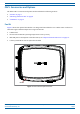
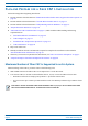
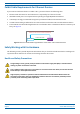

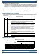
Table Of Contents
- Table of Contents
- Document Overview
- Era System Overview
- Fiber CAP L Overview
- Plan and Prepare for a Fiber CAP L Installation
- Maximum Number of Fiber CAP Ls Supported in an Era System
- Cascade Rules for Fiber CAP Ls
- Cat6A Cable Requirements for Ethernet Devices
- Safely Working with Era Hardware
- Determine the Power Consumption of the CAP L
- Determine the CAP L Installation Site
- Recommended Tools and Material
- Unpack and Inspect the CAP L and Optional Accessories
- Obtain the Required Materials
- Mount the Fiber CAP L
- General Mounting Cautions
- Mounting a CAP L with a Flat Mounting Bracket Kit
- Mounting Two CAP Ls with a Dual Mounting Kit
- Mounting a CAP L with an AC/DC Power Supply Kit
- Wiring the AC/DC Power Supply Kit.
- Mounting a CAP L with a Hybrid Fiber Splice Box Kit
- Prepare for CAP L Hybrid Fiber Splice Box Kit Installation
- Assembling and Wiring the Hybrid Fiber Splice Box
- Wire the Hybrid Fiber Splice Box
- Wire a Hybrid Fiber Splice Box for 4-Wire Power with Limited Power Source
- Wire a Hybrid Fiber Splice Box for 2-Wire Power without Limited Power Source
- Wire a Hybrid Fiber Splice Box to Cascade Two CAP Ls with the 2-Wire Power Configuration
- Wire a Hybrid Fiber Splice Box to Cascade Two CAP Ls with the 4-Wire Power Configuration
- Wall Mount a CAP L Using a CAP L Hybrid Fiber Splice Box Kit
- Ceiling Mount a CAP L
- Connect the Cables to the Fiber CAP L
- Powering on a Fiber CAP L
- CAP L Maintenance
- Contacting CommScope

CommScope Era
™
Fiber Low Power Carrier Access Point Installation Guide M0201ANC_uc
Page 10 © June 2019 CommScope, Inc.
Plan and Prepare for a Fiber CAP L Installation
PLAN AND PREPARE FOR A FIBER CAP L INSTALLATION
Do the following before beginning installation.
1 Review and know the information in "Maximum
Number of Fiber CAP Ls Supported in an Era System” on
page 10.
1 Rev
iew and know the information in "Cascade R
ules for Fiber CAP Ls” on page 11.
2 Review and know the information in "Saf
ely Working with Era Hardware” on page 12.
3 "Required Antenna Distances” on page 16.
4 "Determine the CAP L Installation Site” on page 17, which includes understanding and meeting
requirements for:
• "Recommended Tools and Material” on page 23
• "CAP L Weights” on page 21
• "Extended CAP L Temperature Operation” on page 22
• "CAP L Dimensions” on page 18.
5 Map out all
cable runs.
6 Identify and obtain all tools and mater
ials required to complete the installation as described in
"Recommended Tools and Material” on page 23.
7 Obtain any accessories required for this installation; see "CAP L Accessories and Options” on page 7.
8 "Unpack and Inspect the CAP L and Optional Accessories” on page 23.
Maximum Number of Fiber CAP Ls Supported in an Era System
When installing a Fiber CAP L, you must observe the following rules.
• SMF or MMF connects the Fiber CAP L via its Op
tical Port 1 to the OPT Card.
• You connect CAP Ls to a
n OPT Card installed in Slots L1, L2, L3, or L4 in the TEN or Classic CAN.
– Each OPT Card has four 10 Gbps ports (labeled 1 - 4) for
fiber connections.
– You can connect up to 4 CAP Ls
per OPT Card for a total of 16 Primary and 32 total, per TEN or Classic
CAN.
Fiber CAP Ls must be connected to OPT Cards installed in Slots L1, L2, L3, or L4 in a TEN or Classic CAN.
OPT Cards installed in WCS Slots L5 - L8 cannot be used to connect APs.