
Installation Guide
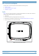
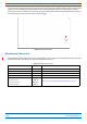
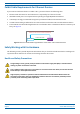

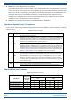
Table Of Contents
- Table of Contents
- Document Overview
- Era System Overview
- Fiber CAP L Overview
- Plan and Prepare for a Fiber CAP L Installation
- Maximum Number of Fiber CAP Ls Supported in an Era System
- Cascade Rules for Fiber CAP Ls
- Cat6A Cable Requirements for Ethernet Devices
- Safely Working with Era Hardware
- Determine the Power Consumption of the CAP L
- Determine the CAP L Installation Site
- Recommended Tools and Material
- Unpack and Inspect the CAP L and Optional Accessories
- Obtain the Required Materials
- Mount the Fiber CAP L
- General Mounting Cautions
- Mounting a CAP L with a Flat Mounting Bracket Kit
- Mounting Two CAP Ls with a Dual Mounting Kit
- Mounting a CAP L with an AC/DC Power Supply Kit
- Wiring the AC/DC Power Supply Kit.
- Mounting a CAP L with a Hybrid Fiber Splice Box Kit
- Prepare for CAP L Hybrid Fiber Splice Box Kit Installation
- Assembling and Wiring the Hybrid Fiber Splice Box
- Wire the Hybrid Fiber Splice Box
- Wire a Hybrid Fiber Splice Box for 4-Wire Power with Limited Power Source
- Wire a Hybrid Fiber Splice Box for 2-Wire Power without Limited Power Source
- Wire a Hybrid Fiber Splice Box to Cascade Two CAP Ls with the 2-Wire Power Configuration
- Wire a Hybrid Fiber Splice Box to Cascade Two CAP Ls with the 4-Wire Power Configuration
- Wall Mount a CAP L Using a CAP L Hybrid Fiber Splice Box Kit
- Ceiling Mount a CAP L
- Connect the Cables to the Fiber CAP L
- Powering on a Fiber CAP L
- CAP L Maintenance
- Contacting CommScope

CommScope Era
™
Fiber Low Power Carrier Access Point Installation Guide M0201ANC_uc
Page 8 © June 2019 CommScope, Inc.
Fiber CAP L Overview
Figure 4 shows the proprietary 8-pin Fan Interface port, which is only available on Fiber CAP L units that ship
with the factory-installed Fan Kit. If the Fiber CAP L being installed includes the Fan Kit option, the Fan
Interfa
ce port will be cabled to the Fan Kit at the factory. If the Fiber CAP L being installed does not inclu
de
the Fan Kit option, the Fan Interface port will be plugged.
Fan
Interface
port
Figure 4. Fan Interface Port
Mounting and Power Kits
CAP L Mounting and Power Kits are not included with the CAP L and must be ordered separately. Mounting
and Power Kits are described in the applicable installation process:
Table 3. Mounting and Power Kits
Mounting/Power Kit CommScope PN See
Flat Mounting Bracket Kit 7774353-xx "Mounting a CAP L with a Flat Mounting Bracket Kit” on page 25
Dual Mounting Kit 7815440-xx "Mounting Two CAP Ls with a Dual Mounting Kit” on page 31
Hybrid Fiber Splice Kit 7781091-xx "Mounting a CAP L with a Hybrid Fiber Spl
ice
Box Kit” on page 43
Power Supply/Hybrid Fiber Mounting Kit 7774354-xx "Mounting a CAP L with an AC/DC Power Supply Kit” on page 38
240W Local AC Power Supply Kit
"Mounting a CAP L with an AC/DC Power Supply Kit” on page 38
no AC Input Cord 7775087-xx
with AC Input Cord 7809798-xx
for Plenum Space 7809823-xx