CommScope Era™ Fiber Low Power Carrier Access Point Installation Guide • M0201ANC_uc • June 2019
DISCLAIMER This document has been developed by CommScope, and is intended for the use of its customers and customer support personnel. The information in this document is subject to change without notice. While every effort has been made to eliminate errors, CommScope disclaims liability for any difficulties arising from the interpretation of the information contained herein.
TABLE OF CONTENTS Document Overview .................................................................................................................................................................................. 1 Document Revision History .............................................................................................................................................................................. 1 Document Cautions and Notes.................................................................
Table of Contents Connect the Cables to the Fiber CAP L...................................................................................................................................................... 55 Ground the Fiber CAP L (Optional) ................................................................................................................................................................. 55 Connect the Fiber CAP L to a Passive RF Antenna ........................................................
D OCUMENT O VERVIEW There are two variants available for Low Power Carrier Access Points (CAP L): one variant has an optical fiber interface (Fiber CAP L), and the other has a copper interface (Copper CAP L). This installation guide provides a product overview and installation instructions for the Fiber CAP L. (For information on the Copper CAP L, refer to the CommScope Era™ Copper Low Power Carrier Access Point Installation Guide; see "Accessing Era/ION-E Series User Documentation” on page 66).
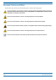
Document Overview Document Cautions and Notes This document may contain any of the following notes, cautions, and warning icons. The icon to the left is used to indicate a caution or warning. Cautions and warnings indicate operations or steps that could cause personal injury, induce a safety problem in a managed device, destroy or corrupt information, or interrupt or stop services. The icon to the left indicates a caution or warning that pertains to laser equipment.
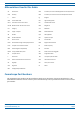
Document Overview Abbreviations Used in this Guide AP Access Point ISDE Innovation, Sciences et Développement économique Canada AUX Auxiliary ISED Innovation, Science and Economic Development Canada C Celsius kg Kilogram CAN Central Area Node LED Light Emitting Diode CAP L Low Power Carrier Access Point LPS Limited Power Source CAP M Medium Power Carrier Access Point MHz Megahertz Cat Category mm Millimeter CAT Copper Transport MMF Multi-Mode Fiber dB Decibel N/A Not Appli
Era System Overview E RA S YSTEM O VERVIEW CommScope Era™ coordinates wireless capacity throughout the entire coverage area via a single centralized head-end location or from an operator’s existing C-RAN hub. Based on ION-E®, Era operates on the same cost-efficient standard IT cabling as ION-E and is compatible with ION-E deployments.
Fiber CAP L Overview F IBER CAP L O VERVIEW There is one Optical Fiber and two Copper CAP L interface variants. This installation guide describes the Fiber CAP L, which interfaces with a Classic CAN or TEN via an optical link. This allows the Fiber CAP L to provide data over Single-Mode Fiber (SMF) or Multi-Mode Fiber (MMF). Power for Fiber CAP Ls is provided over External AC/DC or remotely through hybrid fiber.
Fiber CAP L Overview Connectors and LED for the Fiber CAP L Figure 2 and Table 2 identify the Fiber CAP L connectors and its LED; corresponding connectors are shown. 1 2 9 6 3 7 8 5 4 Figure 2. CAP L Connectors and LED Table 2. Function of the CAP L Connectors and LED REF # Label Description 1, 4 ANT 3, ANT 4 Not available; connector is plugged.
Fiber CAP L Overview CAP L Accessories and Options The Fiber CAP L accessories and options are described in the following sections: • "Fan Kit” on page 7 • "Mounting and Power Kits” on page 8 • "OCTIS Kits” on page 9 Fan Kit Figure 3 shows the optional Fan Kit that is an integrated shroud that fits over a Fiber CAP L enclosure to extend the upper ambient temperature range.
Fiber CAP L Overview Figure 4 shows the proprietary 8-pin Fan Interface port, which is only available on Fiber CAP L units that ship with the factory-installed Fan Kit. If the Fiber CAP L being installed includes the Fan Kit option, the Fan Interface port will be cabled to the Fan Kit at the factory. If the Fiber CAP L being installed does not include the Fan Kit option, the Fan Interface port will be plugged. Fan Interface port Figure 4.
Fiber CAP L Overview OCTIS Kits All Fiber CAP Ls include one OCTIS1 Kit for the primary interface to the Classic CAN or TEN. Regardless of which OCTIS Kit ships with the CAP L, it will plug into Port 1 on the CAP L. You must order an additional OCTIS Kit to cascade two CAP Ls, or to attach an auxiliary Ethernet device; which OCTIS Kit you should order is identified in Table 4. Table 4.
Plan and Prepare for a Fiber CAP L Installation P LAN AND P REPARE FOR A F IBER CAP L I NSTALLATION Do the following before beginning installation. 1 Review and know the information in "Maximum Number of Fiber CAP Ls Supported in an Era System” on page 10. 1 Review and know the information in "Cascade Rules for Fiber CAP Ls” on page 11. 2 Review and know the information in "Safely Working with Era Hardware” on page 12. 3 "Required Antenna Distances” on page 16.
Plan and Prepare for a Fiber CAP L Installation Cascade Rules for Fiber CAP Ls When cascading a Secondary Fiber CAP L or an external Ethernet device such as WiFi or an IP camera, you must observe the following rules. • In a cascade, the CAP L connected directly to the Classic CAN or TEN is the Primary Fiber CAP L, and the CAP L that connects to the Primary Fiber CAP L is the Secondary Fiber CAP L. • The cascaded unit must use the same transport type—you cannot cascade a Copper CAP L to a Fiber CAP L.
Plan and Prepare for a Fiber CAP L Installation Cat6A Cable Requirements for Ethernet Devices If you connect an Ethernet device to a Fiber CAP L, you must observe the following rules. • Plenum rated cable must be used whenever it is required by local electrical codes. • Shielded twisted pair is not required unless operating in a high RFI/EMI environment. • CommScope strongly recommends using factory terminated and tested Cat6A Patch Cord.
Plan and Prepare for a Fiber CAP L Installation Property Damage Warnings Keep operating instructions within easy reach and make them available to all users. Only license holders for the respective frequency range are allowed to operate this unit. Read and obey all the warning labels attached to the unit. Make sure that all warning labels are kept in a legible condition. Replace any missing or damaged labels.
Plan and Prepare for a Fiber CAP L Installation Compliance 1 Notice: For installations, which have to comply with FCC RF exposure requirements, the antenna selection and installation must be completed in a way to ensure compliance with those FCC requirements.
Plan and Prepare for a Fiber CAP L Installation other antenna or transmitter. Users and installers must be provided with antenna installation instructions and transmitter operating conditions for satisfying RF exposure compliance. French: Cet appareil est conforme à FCC Partie15.
Plan and Prepare for a Fiber CAP L Installation 8 Notice: For a Class A digital device or peripheral. This equipment has been tested and found to comply with the limits for a Class A digital device, pursuant to Part 15 of the FCC Rules. These limits are designed to provide reasonable protection against harmful interference when the equipment is operated in a commercial environment.
Plan and Prepare for a Fiber CAP L Installation Determine the Power Consumption of the CAP L Use the power consumption matrix in Table 7 to calculate power consumption for a Fiber CAP L, where • the consumption numbers are at the CAP L power inputs and do not account for feed losses • the maximum consumption numbers in Table 7 do not include the power consumed by any attached auxiliary devices. Both CAP L power consumption and auxiliary device power must be included when calculating feed losses.
Plan and Prepare for a Fiber CAP L Installation CAP L Dimensions Use the dimensions shown in the section applicable to this installation to determine the space required at the mounting site. Mounting Dimensions for a CAP L with the Flat Mounting Bracket Kit 512mm [20.16"] 406mm [15.98"] 120mm [4.72"] 393.13mm [15.48"] 383.34mm [15.09"] 24.11mm [0.95"] 440mm [17.32"] 10mm [0.39"] 4X 144mm [5.67"] 205mm [8.07"] 42.75mm [1.68"] 30mm [1.18"] 2X 30.5mm [1.2"] 114.28mm [4.
Plan and Prepare for a Fiber CAP L Installation Mounting Dimensions for Two CAP Ls Mounted with the Dual Mounting Kit 247mm [9.72"] 538mm [21.2"] 448mm 274mm [17.64"] [10.79"] 325mm [12.8"] 10mm [0.394"] 4X 454mm [17.87"] 486mm [19.13"] M0201ANC_uc © June 2019 CommScope, Inc.
Plan and Prepare for a Fiber CAP L Installation Mounting Dimensions for a CAP L Mounted with the CAP L Hybrid Fiber Splice Box Kit 512mm [20.16"] 390.33mm 460.75mm [18.14"] [15.37"] 383.34mm [15.09"] 424.53mm [16.71"] 188mm [7.4"] 120mm [4.72"] 24mm [0.94"] 2X 30mm 2X [1.18"] 116.3mm [4.58"] 31.5mm [1.24"] 36.75mm [1.45"] 170.19mm [6.7"] CommScope Era™ Fiber Low Power Carrier Access Point Installation Guide Page 20 M0201ANC_uc © June 2019 CommScope, Inc.
Plan and Prepare for a Fiber CAP L Installation Mounting Dimensions for a CAP L Mounted with the AC/DC Power Supply Kit 448mm [17.64"] 120mm [4.72"] 373.89mm [14.72"] 398.3mm [15.68"] 468.12mm [18.43"] 432.45mm [17.03"] 398mm [15.669"] 24mm [0.94"] 2X 87.44mm [3.44"] 30mm 2X [1.18"] 104.73mm [4.12"] 31.5mm [1.24"] 158.42mm [6.24"] 188mm [7.
Plan and Prepare for a Fiber CAP L Installation Extended CAP L Temperature Operation The passively cooled CAP L is rated for a maximum temperature of 40°C (104°F). This temperature range guarantees maximum service life under worst-case load conditions. If necessary, however, it can be operated safely at higher temperatures without exceeding the maximum temperatures of the internal electronic components.
Plan and Prepare for a Fiber CAP L Installation Recommended Tools and Material • Electrostatic Discharge (ESD) wrist strap • Drill and bits to mount the to a wall or ceiling • Fiber cleaning equipment • if required per local practice, insulated stranded copper wire for chassis ground; see "Ground the Fiber CAP L (Optional)” on page 55.
Mount the Fiber CAP L M OUNT THE F IBER CAP L A Fiber CAP L is suitable for indoor and outdoor installations as follows: • Indoors—All versions of the Fiber CAP L can be installed indoors. • Outdoors—Only Fiber CAP Ls with the optional Fan Kit can be installed outdoors. Mounting instructions are divided into the sections listed below.
Mount the Fiber CAP L Mounting a CAP L with a Flat Mounting Bracket Kit Figure 6 shows the Flat Mounting Bracket Kit (CommScope PN 7774353-xx), which provides the mounting brackets required to mount a Fiber CAP L to a wall or other flat surface. Two Moun ng Brackets Six M6-1.0 x 14 mm screws Figure 6. Flat Mounting Bracket Kit (PN 7774353-xx) M0201ANC_uc © June 2019 CommScope, Inc.
Mount the Fiber CAP L Attach the Flat Mounting Bracket Kit to the CAP L Attach the two mounting brackets to the back of the CAP L enclosure as described below and as shown in Figure 7 (Fiber CAP L with a Fan Kit) and Figure 8 on page 27 (Fiber CAP L without Fan Kit). 1 Use "Plan and Prepare for a Fiber CAP L Installation” on page 10 to identify the installation site and installation requirements, and to prepare for this installation.
Mount the Fiber CAP L One Moun ng bracket in ver cal posi on Fan Kit Three M6-1.0 x 14mm screws One Moun ng bracket in ver cal posi on Three M6-1.0 x 14mm screws Figure 8. Fiber AP L with a Fan Kit and Flat Mounting Bracket Kit (PN 7774353-xx) Flat-Surface Mount a CAP L You can place a Fiber CAP L on a flat surface, such as a shelf, desk, cabinet, above a ceiling, or any other horizontal surface that allows stable placement.
Mount the Fiber CAP L Do not stack CAP Ls on top of each other. Always secure the CAP L to the mounting surface. 3 Follow the steps in "Attach the Flat Mounting Bracket Kit to the CAP L” on page 26. 4 Refer to the following graphic to see the correct way to flat-surface mount a Fiber CAP L. Fins facing up Flat-Moun ng Bracket op on secures the CAP L to the flat surface. Flat Surface Mount Ceiling Mount with the CAP L Fins facing down – Fan Kit is recommended.
Mount the Fiber CAP L Wall Mount a CAP L The following sections provide the installation methodology and steps required to mount a Fiber CAP L to a wall. Mounting Orientation for Wall Mounts When wall mounting a Fiber CAP L, the recommendations should be observed. • Wall Mount Orientation for a CAP L without a Fan Kit A CAP L that does not have a Fan Kit is passively cooled. You should therefore mount a CAP L that does not have a Fan Kit with the ANT ports pointing down (see Figure 9).
Mount the Fiber CAP L • Wall Mount Orientation for a CAP L with a Fan Kit—To allow for optimal access to the CAP L cables, it is recommended that a Fiber CAP L with the Fan Kit option be mounted with the ANT ports are pointing to the left; see Figure 10. ANT connectors poin ng to the le Figure 10. Mounting Orientation for a CAP L with the Optional Fan Kit (Flat Mounting Bracket Shown) Mounting requirements for flat surfaces are described in "Flat-Surface Mount a CAP L” on page 27.
Mount the Fiber CAP L 5 Use four 5/16-inch or M8 lag screws (or whatever screw type is appropriate for the material to which the Fiber CAP L is to be mounted on) to mount the CAP L to the wall. 6 After you mount the Fiber CAP L on a flat surface, follow the steps in • "Ground the Fiber CAP L (Optional)” on page 55 (if grounding is required or preferred) • "Connect the Passive RF Antenna” on page 59.
Mount the Fiber CAP L In this procedure you will mount two Fiber CAP Ls back-to-back in a single mounting bracket. The steps in this procedure will identify the two CAP Ls as CAP L-1 and CAP L-2, as shown in Figure 12. CAP L-1 (front of the CAP L-1 faces the moun ng surface) CAP L-2 (back-to-back with the CAP L-1) Figure 12. Two CAP Ls Back-to-Back in a Dual Mounting Bracket Do the following to mount two Fiber CAP Ls in a Dual Mounting Bracket.
Mount the Fiber CAP L 5 Secure the Dual Wall Mount Bracket (shown below) to the wall (or other suitable vertical surface), as described below. a Install the Dual Wall Mount Bracket using 4 M8 (or 5/16”) screw anchors (not included) or suitable lag bolts according to the drilling layout, as shown below. The M6 screw anchors do not ship with the CAP L as the anchor type is dependent on the on-site conditions (wall structure and materials). Use screw anchors that are rated for the mounting surface. 454.
Mount the Fiber CAP L 6 Use the six M6-1.0 x14mm screws that came with the Dual Mounting Bracket Kit to attach the two Mounting Adapters (three screws per bracket) to the vertical M6-1.0 mounting taps on the back of the CAP L-1 chassis (three taps per side). Moun ng Adapter Three M6-1.0 x 14mm screws Moun ng Adapter Three M6-1.0 x 14mm screws CommScope Era™ Fiber Low Power Carrier Access Point Installation Guide Page 34 M0201ANC_uc © June 2019 CommScope, Inc.
Mount the Fiber CAP L 7 Insert an M8x16 screw in the top screw hole on the left Mounting Adapter attached to CAP L-1, and then insert screw three or four turns. M8x16 screw Moun ng Adapter M8x16 screw Moun ng Adapter 8 Repeat Step 7 for the right Mounting Adapter. M0201ANC_uc © June 2019 CommScope, Inc.
Mount the Fiber CAP L 9 Do the following to mount CAP L-1 in the Wall Bracket. a Holding the CAP L-1 with the front of the chassis facing the mounting surface, lift it above the Mounting Bracket attached to the wall, and then lower it into place, aligning the M8x16 screws that you attached to the Mounting Adapters in Step 7 on page 35 and Step 8 on page 35 with the Mounting Bracket slots that are closest to the mounting surface.
Mount the Fiber CAP L d Confirm that the CAP L-1 is securely attached to the Dual Wall Mount Bracket, as shown in the following graphic. 10 Repeat Step 6 on page 34 through Step 9 on page 36 to mount the CAP L-2 chassis in the Dual Wall Mounting Bracket; install the CAP L-2 chassis back-to-back with the CAP L-1 chassis, as shown Figure 12 on page 32.
Mount the Fiber CAP L Mounting a CAP L with an AC/DC Power Supply Kit An AC/DC Power Supply Kit provides a 48V External Power Supply that converts local AC power to DC power for the CAP L. An AC/DC Power Supply Kit can be used for a Fiber or Copper Interface when an AC power source is located near the CAP L. Figure 13. CAP L with AC/DC Power Supply Kit Do the following to mount a CAP L using an AC/DC Power Supply Kit. 1 Obtain the AC/DC Power Supply Kit that is appropriate for this installation.
Mount the Fiber CAP L 240W Local AC Power Supply Kit, No AC Cord (CommScope PN 7775087-xx) AC Input power cord to be supplied by the installer. 240W Local AC Power Supply Kit with AC Input Cord (CommScope PN 7809798-xx) 3m AC input cord is connected internally to PSU but unterminated at customer end. 240W Local AC Power Supply Kit for Plenum Space (CommScope PN 7809823-xx) Not for outdoor use! Figure 14.
Mount the Fiber CAP L 2 Insert a 16 AWG (1.31 mm2) 3-conductor AC input cable through the cable gland in the junction box. A plenum rated AC input cable is required when using the Plenum AC Power Supply kit or else the cable must be routed to the junction box in conduit. 3 Terminate the cables using WAGO 221 Series Lever-Nuts or equivalent connectors as shown in Figure 16. WAGO 221 SERIES LEVER-NUTS OR EQUIV. SEE CONNECTION DIAGRAM AT RIGHT. POWER SUPPLY (5 mm) AC INPUT CABLE Figure 16.
Mount the Fiber CAP L Two Angled Moun ng Brackets Four M8x16 flange-head screws Six M6-1.0 x 14mm screws AC/DC Power Supply Unit with Junc on Box Four M6-1.0 x 14mm screws Local Power Jumper Cable Power Supply/ Hybrid Fiber Moun ng Kit Figure 17. CAP L (No Fan Kit) with AC/DC Power Supply Kit (PN 7775087-xx) and Power Supply/Hybrid Fiber Mounting Kit (7774354-xx) The Power Supply/Hybrid Fiber Mounting Kit is not included with the CAP L and must be ordered separately.
Mount the Fiber CAP L Two Angled Moun ng Brackets Fan Kit Four M8x16 flange-head screws Six M6-1.0 x 14mm screws Four M4x8 screws AC/DC Power Supply Unit with Junc on Box Power Supply/ Hybrid Fiber Moun ng Kit Local Power Jumper Cable Figure 18. CAP L with Fan Kit, AC/DC Power Supply Kit (PN 7775087-xx) and Power Supply/Hybrid Fiber Mounting Kit (PN 7774354-xx) 8 Connect the Local Power Jumper Cable (shown below) to the CAP L 36 to 60 Vdc Power connector (see Figure 2 on page 6).
Mount the Fiber CAP L Mounting a CAP L with a Hybrid Fiber Splice Box Kit The CAP L Hybrid Fiber Splice Box Kit (CommScope PN 7781091-xx) provides a connection solution for both power and optical signals to a CAP L. For Fiber CAP Ls, you have the option to use composite cable to transport signals from a TEN or Classic CAN via fiber and power from a remote DC supply, and then use the CAP L Hybrid Fiber Splice Box Kit to terminate the power and fiber at the CAP L.
Mount the Fiber CAP L Wire the Hybrid Fiber Splice Box Do the following to assemble and wire the Hybrid Fiber Splice Box. 1 Open the Hybrid Fiber Splice Box and remove the installation kit that is inside. 2 Using the parts from the Hybrid Fiber Splice Box, insert the Splice Holder and fasten it using a PTK 30x6 screw and one M4 washer. 3 From the CAP L Hybrid Fiber Splice Box Kit, insert Fiber Patch Cord in one of the cable glands indicated in the graphic to the right.
Mount the Fiber CAP L 5 Insert the composite cable in the first cable gland and separate the multi-fibers cable from the copper wires. It is necessary to remove the nut to perform this action. The cable must be fed through the nut and it must be retightened once finished. 6 Bend the spliced fibers using the corner guides and fix the splices to the splice holder. 7 Bend the optical cables as shown in the picture to the right.
Mount the Fiber CAP L 10 Place each cable into one of the grooves of the seal insert. 11 Press the seal insert into the clamp ring opening. 12 Fix the optical cables inside the box using one cable tie and tight the sealing nut. 13 It is possible to separate the optical cables and use two different cable glands. Remove the sealing nut and rubber on each cable gland. 14 Close all unused grooves with the plastic cylinders, no matter if one or two cable glands are used.
Mount the Fiber CAP L 16 Remove the sealing nut and insert the CAP L supply cable and tighten the sealing nut. 17 Connect the supply cable to the terminal strip and fix it inside the box using one cable tie. It is possible to connect a second supply cable to cascade two CAP Ls, as shown in the graphic to the right. 18 Complete the steps in "Wall Mount a CAP L Using a CAP L Hybrid Fiber Splice Box Kit” on page 52.
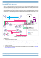
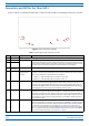
Mount the Fiber CAP L 1 Refer to Table 10 and Figure 19 to wire a Hybrid Fiber Splice Box for 4-Wire power with Limited Power Source (LPS). All four pins of the proprietary CAP L 4-pin 36 to 60 Vdc Power connector must be terminated. Table 10.
Mount the Fiber CAP L Wire a Hybrid Fiber Splice Box for 2-Wire Power without Limited Power Source Each CAP L can be powered by 2 wires if LPS from the DC PSU are not required by local regulations.. All four pins of the proprietary CAP L 4-pin 36 to 60 Vdc Power connector must be terminated. 1 Refer to Table 11 and Figure 20 to wire a Hybrid Fiber Splice Box for 2-Wire power without an Limited Power Source (LPS).
Mount the Fiber CAP L 2 After you have wired the Hybrid Fiber Splice box, complete the steps in "Wall Mount a CAP L Using a CAP L Hybrid Fiber Splice Box Kit” on page 52. Wire a Hybrid Fiber Splice Box to Cascade Two CAP Ls with the 2-Wire Power Configuration Figure 21 shows a variation of the 2-Wire power configuration that allows you to cascade two CAP Ls using a single 4-wire hybrid cable. All four pins of the proprietary CAP L 4-pin 36 to 60 Vdc Power connector must be terminated.
Mount the Fiber CAP L Wire a Hybrid Fiber Splice Box to Cascade Two CAP Ls with the 4-Wire Power Configuration Figure 22 shows a variation of the 4-Wire power configuration that allows you to cascade two CAP Ls using two 4-wire hybrid cables. All four pins of the proprietary CAP L 4-pin 36 to 60 Vdc Power connector must be terminated. Hybrid Fiber/Composite cable One wire each for the Main and Secondary CAP L in the cascade Figure 22.
Mount the Fiber CAP L Wall Mount a CAP L Using a CAP L Hybrid Fiber Splice Box Kit 1 Attach the Hybrid Fiber Splice Box to the Wall Bracket with the three captive screws already installed in the Splice Box. Connect three cap ve screws on Hybrid Fiber Splice Box to Wall Bracket 2 Attach the assembled Wall Mounting Bracket and Hybrid Splice Box to the selected mounting location. 3 Use the six M6-1.0 x14mm screws to attach the two Angled Mounting Brackets to the back of the CAP L, as shown below.
Mount the Fiber CAP L The following graphic provides an exploded view of how the different components of the Hybrid Splice Box Mounting Kit come together. Angled Moun ng Bracket Flange-head screw M6-1.0 x14mm screw Hybrid Fiber Splice Box Wall Bracket 4 Put a flange-head screw halfway into the top screw holes on the side of the Angled Mounting Brackets.
Mount the Fiber CAP L Ceiling Mount a CAP L You can mount a CAP L above or below a ceiling. When installing a CAP L below a ceiling, the use of the optional Fan Kit determines how the CAP L can be ceiling mounted, as described in the following sections. • "Ceiling Mount a CAP L without a Fan Kit” on page 54 • "Ceiling Mount a CAP L with a Fan Kit” on page 54. If you mount the CAP L above the ceiling, its antennas must protrude below the ceiling.
Connect the Cables to the Fiber CAP L C ONNECT THE C ABLES TO THE F IBER CAP L Complete the following procedures in the order in which they are presented. Unless otherwise noted, each procedure is applicable to a singular Fiber CAP L (not in a cascade), or to a Primary or Secondary CAP L in a cascade.
Connect the Cables to the Fiber CAP L 5 Attach the ring end of the wire to the chassis ground stud, as shown in the graphic below. Ground stud 6 Use the Keps nut removed in Step 4 to secure the ground wire to the chassis-ground stud. 7 Route the free end of the chassis grounding wire to an approved (per local code or practice) earth ground source.
Connect the Cables to the Fiber CAP L Clean the RF Cable Connectors This section tells you how to clean RF cable connectors. The graphics in this section illustrate the cleaning procedure and do not show the CAP M. This procedure requires the use of compressed air. Wear protective clothing—especially protective glasses—to protect against injury from flying particles. This procedure requires the use of flammable material. There is a risk of fire. Keep away from sources of ignition.
Connect the Cables to the Fiber CAP L 4 Use a lint-free wipe drenched with isopropyl alcohol to clean the connector winding. 5 Use a cotton bud drenched with isopropyl alcohol to clean the lip of the inner ring. 6 Use a cotton bud drenched with isopropyl alcohol to clean the inside surface of the inner ring. 7 Use a cotton bud drenched with isopropyl alcohol to clean the inside of the center conductor spring tines.
Connect the Cables to the Fiber CAP L 9 Use compressed air to remove metal chips and small particles from the mating and inner surfaces of the connector. 10 Use a lint-free wipe drenched with isopropyl alcohol to clean the winding area. 11 Use a cotton bud drenched with isopropyl alcohol to clean the inside mating surface of the inner ring. 12 Use a cotton bud drenched with isopropyl alcohol to clean the outside surface of the center pin.
Connect the Cables to the Fiber CAP L Do the following to connect a Fiber CAP L to a passive RF antenna. 1 Connect the CAP L ANT 1 or ANT 2 connector to a passive RF antenna. a Locate the 50 coaxial cables obtained for this installation; see "Obtain the Required Materials” on page 23. b Install the passive antennas per the manufacturer’s installation instructions.
Connect the Cables to the Fiber CAP L ii e Connect that end of the SMF or MMF to the CAP L Optical Port 1 connector. (Refer to the technical data sheet that ships with the OCTIS Kit for further information.) Connect the other end of the SMF or MMF to an open port on an OPT Card installed in Slots L1-L4 in the TEN or Classic CAN. WCS Slots L5-L8 cannot be used to connect APs.
Powering on a Fiber CAP L Connect an External Ethernet Device (Optional) If you are not connecting an Ethernet device, do not remove the plug from Port A. If connecting an Ethernet device to a cascaded pair, this must be the Primary Fiber CAP L. 1 Read and follow the rules in "Cat6A Cable Requirements for Ethernet Devices” on page 12. 2 Raise the lever on the EMI/IP67 cap on the Port A connector, and then remove the connector’s plug. 3 Follow the local cleaning technique to clean Port A.
CAP L Maintenance CAP L M AINTENANCE The following sections tell you how to remove a CAP L from mounting brackets and provides preventative maintenance instructions. Remove a CAP L from a Wall or Ceiling Mount Should you need to remove the CAP L from a wall or ceiling mount, do the following. 1 Unplug the CAP L cables. 2 If a ground wire is installed, loosen the grounding screw and remove the ground wire. 3 Reverse the installation steps that correspond to how this CAP L is mounted.
Contacting CommScope C ONTACTING C OMM S COPE The following sections tell you how to contact CommScope for additional information or for assistance. CMS Global Technical Support The following sections tell you how to contact the CommScope Mobility Solutions (CMS) Technical Support team. Support is available 7 days a week, 24 hours a day. Telephone Helplines Use the following Helpline telephone numbers to get live support, 24 hours a day: 24x7 +1 888-297-6433 (Toll free for U.S.
Contacting CommScope Hardware to Software Mapping Information 1 Scan the QR Code to the right to view or download the minimum software requirements for each of the DCCS hardware modules. Alternatively, you can go to the following web address to access the portal: http://www.commscope.com/collateral/DCCS_HW_SW_Mapping/ 2 Click on a document link to open it, or right click on the link and select the Save target as… option from the contextual menu.
Contacting CommScope Accessing Era/ION-E Series User Documentation 1 Scan the QR Code to the right to go directly to the CommScope DCCS Customer Portal, where you can access the DCCS user documentation. Alternatively, you can go to the following web address to access the portal: https://www.mycommscope.com 2 Access to the Customer Portal requires a user account and password.