
Installation Guide
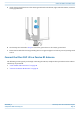

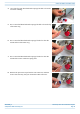
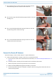
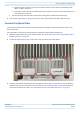
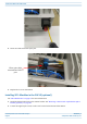
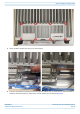
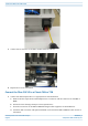


Table Of Contents
- Table of Contents
- Document Overview
- Fiber CAP L2 Overview
- Plan and Prepare for a Fiber CAP L2 Installation
- Mount the Fiber CAP L2
- General Mounting Cautions
- Mounting CAP L2 with a Wall Mounting Kit
- Mounting a CAP L2 with an AC/DC Power Supply Kit
- Wiring the AC/DC Power Supply Kit
- Mounting a CAP L2 with a Hybrid Fiber Splice Box Kit (optional)
- Connect the Cables to the Fiber CAP L2
- Powering on a Fiber CAP L2
- Contacting CommScope

M0203A9B_uc CommScope ERA
®
CAP L2 with Fiber Interface
© September 2022 CommScope, Inc. Page 45
Powering on a Fiber CAP L2
i Follow the limitations per the maximum range described in "OCTIS Universal Lever Assembly
Instructions” on page 13.
ii Connect that end of the SMF or MMF to the CAP L2 Optical Port 1 connector.
e Connect the other end of the SMF or MMF to an open port on an OPT Card installed in Slots L1-L4 in
the TEN or Classic CAN. WCS Slots L5-L8 cannot be used to connect APs.
2 Go to "Connect to Vdc Power” on page 45.
Connect to Vdc Power
Connect the Vdc Power connector as appropriate for this installation. The CAP L2 is powered on as soon as
you connect the CAP L2 to a power source; see "Powering on a Fiber CAP L2” on page 45.
• If powering the CAP L2s with local AC/DC power adapters, please see "Wiring the AC/DC Power Supply
Kit” on page 25.
• If powering the CAP L2s with the Hybrid Fiber Splice Box kits, please see "Mounting a CAP L2 with a
Hybrid Fiber Splice Box Kit (optional)” on page 28.
POWERING ON A FIBER CAP L2
The CAP L2 is powered on as soon as power is connected to it. Under normal operating conditions, the Power
LED turns on briefly when the unit is first detected. It will then go out briefly, followed by an initialization
period during which the Power LED flashes slowly while the CAP L2 is configured. The Power LED remains a
steady green (not flashing) once the unit reaches a fully operational state, which typically occurs within 45
seconds.
The Power LED behavior for a Fiber CAP L2 is as follows:
• Steady Green – CAP/UAP is on and operational
• Slow Flashing Green – The CAP/UAP has been powered on and is initializing or if it is updating software.
• Fast Flashing green – The CAP unit identifier is active via the Flash LED function in the Era GUI.
• Slow-Flashing Red – The Era GUI is reporting a critical alarm for the unit. The CAP can be recovered
without replacing hardware.
• Steady Red – The Era GUI is reporting a critical alarm for the unit. The CAP or CAP component (e.g SFP+
module) must be replaced.
If installing a CAP L2 with the CAP L2 Hybrid Fiber Splice Box Kit (PN 7781091-xx), the optical fiber will be
hanging from the Hybrid Fiber Splice Box.