
Installation Guide
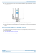

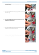
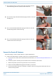
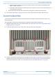
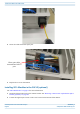
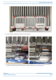
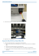


Table Of Contents
- Table of Contents
- Document Overview
- Fiber CAP L2 Overview
- Plan and Prepare for a Fiber CAP L2 Installation
- Mount the Fiber CAP L2
- General Mounting Cautions
- Mounting CAP L2 with a Wall Mounting Kit
- Mounting a CAP L2 with an AC/DC Power Supply Kit
- Wiring the AC/DC Power Supply Kit
- Mounting a CAP L2 with a Hybrid Fiber Splice Box Kit (optional)
- Connect the Cables to the Fiber CAP L2
- Powering on a Fiber CAP L2
- Contacting CommScope

M0203A9B_uc CommScope ERA
®
CAP L2 with Fiber Interface
© September 2022 CommScope, Inc. Page 37
Connect the Cables to the Fiber CAP L2
5 Attach the ring end of the wire to the chassis ground stud on the bottom, right side of the CAP L2, as shown
in the graphic below.
6 Use the Keps nut removed in Step 4 to secure the ground wire to the chassis-ground stud.
7 Route the free end of the chassis grounding wire to an approved (per local code or practice) earth ground
source.
Connect the Fiber CAP L2 to a Passive RF Antenna
The following sections guide you through connecting the CAP L2; complete these procedures in the order in
which they are presented.
• "Clean the RF Cable Connectors” on page 38
• "Connect the Passive RF Antenna” on page 40