
Installation Guide


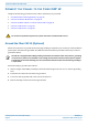
Table Of Contents
- Table of Contents
- Document Overview
- Fiber CAP L2 Overview
- Plan and Prepare for a Fiber CAP L2 Installation
- Mount the Fiber CAP L2
- General Mounting Cautions
- Mounting CAP L2 with a Wall Mounting Kit
- Mounting a CAP L2 with an AC/DC Power Supply Kit
- Wiring the AC/DC Power Supply Kit
- Mounting a CAP L2 with a Hybrid Fiber Splice Box Kit (optional)
- Connect the Cables to the Fiber CAP L2
- Powering on a Fiber CAP L2
- Contacting CommScope

CommScope ERA
®
CAP L2 with Fiber Interface M0203A9B_uc
Page 34 © September 2022 CommScope, Inc.
Mount the Fiber CAP L2
2 After you have wired the Hybrid Fiber Splice box, complete the steps in "Wall Mount a CAP L2 Using a
CAP L2 Hybrid Fiber Splice Box Kit (optional)” on page 35.
Wire a Hybrid Fiber Splice Box for 2-Wire Power without Limited Power Source
Each CAP L2 can be powered by 2 wires if LPS from the DC PSU are not required by local regulations..
1 Refer to Table 14 and Figure 13 to wire a Hybrid Fiber Splice Box for 2-Wire power without an Limited
Power Source (LPS).
In this power variation you must tie the following power cables together:
• V1+ (PIN 1) and V2+ (PIN 3) (CAP L2 DC Jumper Power Cable Red and White wires)
• V1- (PIN 2) and V2- (PIN 4) (CAP L2 DC Jumper Power Cable Black and Green wires)
Figure 13. Wiring a Hybrid Fiber Splice Box for 2-Wire Power without LPS
All four pins of the proprietary CAP L2 4-pin 36 to 60 Vdc Power connector must be terminated.
Table 14. Wiring Single Circuit Source to a CAP L2
Source Cable
CAP L Power Cable
Connector
Wire Wire Pin Function
Circuit 1 (0V)
Red 1 V1+
White 3 V2+
Circuit 1 (-36 to -60V)
Black 2 V1-
Green 4 V2-
Pin 1
Pin 2
Pin 4
Pin 3
Connector End View
PIN 1
RED
PIN 2
BLACK
PIN 3
WHITE
PIN 4
GREEN
Three-posion wire connectors
(such as, Wago 221-413)
Hybrid Fiber/Composite
cable
Color code of hybrid cable may
differ from example shown.