
Installation Guide

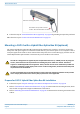
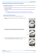

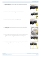


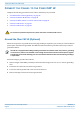
Table Of Contents
- Table of Contents
- Document Overview
- Fiber CAP L2 Overview
- Plan and Prepare for a Fiber CAP L2 Installation
- Mount the Fiber CAP L2
- General Mounting Cautions
- Mounting CAP L2 with a Wall Mounting Kit
- Mounting a CAP L2 with an AC/DC Power Supply Kit
- Wiring the AC/DC Power Supply Kit
- Mounting a CAP L2 with a Hybrid Fiber Splice Box Kit (optional)
- Connect the Cables to the Fiber CAP L2
- Powering on a Fiber CAP L2
- Contacting CommScope

CommScope ERA
®
CAP L2 with Fiber Interface M0203A9B_uc
Page 28 © September 2022 CommScope, Inc.
Mount the Fiber CAP L2
9 Follow the steps in "Ground the Fiber CAP L2 (Optional)” on page 36 if grounding is required or preferred.
10 Follow the steps in "Connect the Passive RF Antenna” on page 40.
Mounting a CAP L2 with a Hybrid Fiber Splice Box Kit (optional)
The CAP L2 Hybrid Fiber Splice Box Kit (CommScope PN 7781091-xx) provides a connection solution for
both power and optical signals to a CAP L2. For Fiber CAP L2s, you have the option to use composite cable to
transport signals from a TEN or Classic CAN via fiber and power from a remote DC supply, and then use the
CAP L2 Hybrid Fiber Splice Box Kit to terminate the power and fiber at the CAP L2.
Prepare for CAP L2 Hybrid Fiber Splice Box Kit Installation
1 Follow the steps in "Unpack and Inspect the CAP L2 and Optional Accessories” on page 18.
2 Refer to "Determine the CAP L2 Installation Site” on page 16 to determine the mounting location, which
must be able to support the weight and dimensions of the CAP L.
3 Refer to "Mounting Orientation for Wall Mounts” on page 20 to determine the mounting orientation of the
CAP L2.
The CAP L2 is designed to be supplied by two LPS (Limited Power Source, <100VA) circuits. By using LPS
circuits, some electrical code requirements for installing the power cables are relaxed. The CAP L2
supports a combined/parallel circuit approach. That is, two LPS circuits can be combined in parallel and
the CAP L2 supplied by a single, higher power source. In either configuration, all electrical and safety code
requirements must be followed.
It is the responsibility of the customer/installer to observe the local regulations of the DC service provider
and to comply with Limited Power Source (LPS) requirements where applicable.
Local Power Jumper that connects
to CAP L 36 to 60 Vdc Power connector
Gland for incoming AC power
L
oca
l
Power Jumper t
h
at connects
o
C
AP
L
3
6
to
6
0
Vd
c
Po
we
r
co
nn
ec
to
r
n
coming AC powe
r