
Installation Guide


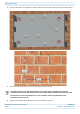
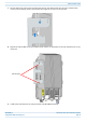
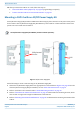
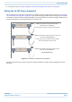
Table Of Contents
- Table of Contents
- Document Overview
- Fiber CAP L2 Overview
- Plan and Prepare for a Fiber CAP L2 Installation
- Mount the Fiber CAP L2
- General Mounting Cautions
- Mounting CAP L2 with a Wall Mounting Kit
- Mounting a CAP L2 with an AC/DC Power Supply Kit
- Wiring the AC/DC Power Supply Kit
- Mounting a CAP L2 with a Hybrid Fiber Splice Box Kit (optional)
- Connect the Cables to the Fiber CAP L2
- Powering on a Fiber CAP L2
- Contacting CommScope

CommScope ERA
®
CAP L2 with Fiber Interface M0203A9B_uc
Page 18 © September 2022 CommScope, Inc.
Plan and Prepare for a Fiber CAP L2 Installation
Recommended Tools and Material
• Electrostatic Discharge (ESD) wrist strap
• Drill and bits to mount the CAP L2 bracket to a wall
• Fiber cleaning equipment
Unpack and Inspect the CAP L2 and Optional Accessories
1 Inspect the exterior of the shipping container(s) for evidence of rough handling that may have damaged
the components in the container.
2 Unpack each container while carefully checking the contents for damage and verify with the packing slip.
3 If damage is found or parts are missing, file a claim with the commercial carrier and notify CommScope
Technical Support (see "CMS Global Technical Support” on page 46). Save the damaged cartons for
inspection by the carrier.
4 Save all shipping containers for use if the equipment requires shipment at a future date.
Obtain the Required Materials
Contact your local CommScope sales representative to obtain the following components, as required, for this
installation.
• Obtain the cable required for this installation.
– Per the installation plan, obtain either Single Mode Fiber (SMF) or Multi Mode Fiber (MMF) that is of
sufficient length to reach from the CAP L2 to the Classic CAN or TEN.
– Per the installation plan, obtain 50
coaxial cables that are of sufficient length to reach from the
CAP L2 to the passive RF antenna. The end of the 50
coaxial cable that will connect to the ANT
connector can be either a push-pull connector or a threaded connector.
• Obtain the Optical OCTIS Kits required for this installation; see "OCTIS™ Universal Lever Assembly Kits”
on page 13.
• Obtain SFP+ Module pairs that are appropriate for this installation; see Table 8.
• Obtain the Mounting Kits for the installation. Mounting Kits are not included with the CAP L2 and must be
ordered separately.
Table 11. Maximum CAP L2 Installation Weights*
CAP L2 configured with this kit …
Maximum Lift
Weight
Total Hanging
Weight
kg lbs. kg lbs.
Single Mounting Bracket 15 33 16.8 37
AC/DC Power Supply Kit TBD TBD TBD TBD