
Installation Guide
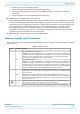
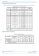
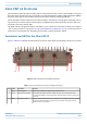
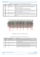
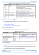
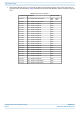


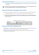
Table Of Contents
- Table of Contents
- Document Overview
- Fiber CAP L2 Overview
- Plan and Prepare for a Fiber CAP L2 Installation
- Mount the Fiber CAP L2
- General Mounting Cautions
- Mounting CAP L2 with a Wall Mounting Kit
- Mounting a CAP L2 with an AC/DC Power Supply Kit
- Wiring the AC/DC Power Supply Kit
- Mounting a CAP L2 with a Hybrid Fiber Splice Box Kit (optional)
- Connect the Cables to the Fiber CAP L2
- Powering on a Fiber CAP L2
- Contacting CommScope

CommScope ERA
®
CAP L2 with Fiber Interface M0203A9B_uc
Page 16 © September 2022 CommScope, Inc.
Plan and Prepare for a Fiber CAP L2 Installation
– Depending on the transmit bandwidth requirements, you can connect up to four CAP L2s to each
OPT Card.
Determine the Power Consumption of the CAP L2
Use the power consumption matrix in Table 10 to calculate power consumption for a Fiber CAP L2, where
• the consumption numbers are at the CAP L2 power inputs and do not account for feed losses
• the maximum consumption numbers in Table 10 do not include the power consumed by any attached
auxiliary devices. Both CAP L2 power consumption and auxiliary device power must be included when
calculating feed losses.
Determine the CAP L2 Installation Site
When deciding on a suitable mounting site, observe the following rules; refer also to "Mounting Orientation
for Wall Mounts” on page 20. The Fiber CAP L2 is suitable for indoor installation.
The following sections provides weight and dimension requirements needed to determine the best
installation site for the Fiber CAP L2.
Fiber CAP L2s must be connected to OPT Cards installed in Slots L1, L2, L3, or L4 in a TEN or Classic CAN.
OPT Cards installed in WCS Slots L5 - L8 cannot be used to connect APs.
Table 10. CAP L2 Fiber Power Consumption
Configuration Voltage Range (V) Typical Power (W) Maximum Power (W)
Fiber CAP L2
1
36 Vdc to 60 Vdc 125 150
1 Does not include consumption of optional local DC supply.