
Installation Guide
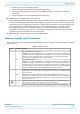
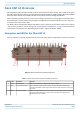
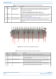
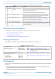

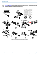

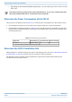
Table Of Contents
- Table of Contents
- Document Overview
- Fiber CAP L2 Overview
- Plan and Prepare for a Fiber CAP L2 Installation
- Mount the Fiber CAP L2
- General Mounting Cautions
- Mounting CAP L2 with a Wall Mounting Kit
- Mounting a CAP L2 with an AC/DC Power Supply Kit
- Wiring the AC/DC Power Supply Kit
- Mounting a CAP L2 with a Hybrid Fiber Splice Box Kit (optional)
- Connect the Cables to the Fiber CAP L2
- Powering on a Fiber CAP L2
- Contacting CommScope

M0203A9B_uc CommScope ERA
®
CAP L2 with Fiber Interface
© September 2022 CommScope, Inc. Page 15
Plan and Prepare for a Fiber CAP L2 Installation
Figure 4. OCTIS Universal Lever Unmating Instructions
PLAN AND PREPARE FOR A FIBER CAP L2 INSTALLATION
Do the following before beginning installation.
1 Review and know the information in "Maximum Number of Fiber CAP L2s Supported in an ERA System”
on page 15.
2 Review and know the information in "Safely Working with ERA Hardware” on page 3.
3 "Determine the CAP L2 Installation Site” on page 16, which includes understanding and meeting
requirements for:
• "Recommended Tools and Material” on page 18
• "CAP L2 Weights” on page 17
• "Recommended Tools and Material” on page 18
• "CAP L2 Dimensions” on page 17.
4 Map out all cable runs.
5 Identify and obtain all tools and materials required to complete the installation as described in
"Recommended Tools and Material” on page 18.
6 Obtain any accessories required for this installation; see "CAP L2 Accessories and Options” on page 11.
7 "Unpack and Inspect the CAP L2 and Optional Accessories” on page 18.
Maximum Number of Fiber CAP L2s Supported in an ERA System
When installing a Fiber CAP L2, you must observe the following rules.
• SMF or MMF connects the Fiber CAP L2 via its Optical Port to the OPT Card.
If the total used signal bandwidth is more than 320MHz a second fiber link is needed. It is connected to Optical
Port 2.
• You connect CAP L2s to an OPT Card installed in Slots L1, L2, L3, or L4 in the TEN or Classic CAN.
– Each OPT Card has four 10 Gbps ports (labeled 1 - 4) for fiber connections.