
Installation Guide
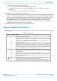
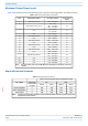
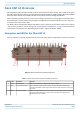
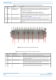
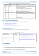
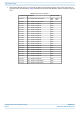

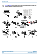

Table Of Contents
- Table of Contents
- Document Overview
- Fiber CAP L2 Overview
- Plan and Prepare for a Fiber CAP L2 Installation
- Mount the Fiber CAP L2
- General Mounting Cautions
- Mounting CAP L2 with a Wall Mounting Kit
- Mounting a CAP L2 with an AC/DC Power Supply Kit
- Wiring the AC/DC Power Supply Kit
- Mounting a CAP L2 with a Hybrid Fiber Splice Box Kit (optional)
- Connect the Cables to the Fiber CAP L2
- Powering on a Fiber CAP L2
- Contacting CommScope

CommScope ERA
®
CAP L2 with Fiber Interface M0203A9B_uc
Page 10 © September 2022 CommScope, Inc.
Fiber CAP L2 Overview
Figure 2. CAP L2 Connectors and LED (4 antennas)
3 None Proprietary 4-pin DC
power connector
Connects to a local or remote DC power supply. The CAP L2 does not ship with any
power cables preinstalled; you need to order the power cable assembly that is
appropriate for this installation.
• 7774061: Cable Assembly, CAP L Local Power Jumper, 0.5 m
• 7816237-xx: Cable Assembly, CAP L Local Power Jumper, 3.0 m
4 ANT 2 4.3-10 RF connector Connect to external antennas or to one of the ports on a multiple input cross-polarized
antenna via 50Ω coaxial cable. The antenna ports ship with dust caps that can be
discarded upon unit installation.
5 None Power and Status LED See "Connectors and LED for the Fiber CAP L2” on page 9
6 Port 2 Port 2 OCTIS Connector Port to pass fiber cable to the SFP+ module. The port seal is the OCTIS Universal
connector PN 7847069. Connecting the fiber cable to the CAP L2 requires removing the
service lid.
Table 6. Function of the CAP L2 Connectors and LED (4 antennas)
Ref # Label Description Function
0 None Grounding Bolt Connects the CAP MX to an approved earth-ground source.
1
Port 1 Port 2 OCTIS Connector Port to pass fiber cable to the SFP+ module. The port seal is the OCTIS Universal
connector PN 7847069. Connecting the fiber cable to the CAP L2 requires
removing the service lid.
2
ANT 1 4.3-10 RF connector Connect to external antennas or to one of the ports on a multiple input
cross-polarized antenna via 50Ω coaxial cable. The antenna ports ship with
dust caps that can be discarded upon unit installation.
3
ANT 2 4.3-10 RF connector Connect to external antennas or to one of the ports on a multiple input
cross-polarized antenna via 50Ω coaxial cable. The antenna ports ship with
dust caps that can be discarded upon unit installation.
Table 5. Function of the CAP L2 Connectors and LED (2 antennas) (Continued)
Ref # Label Description Function
8
7
6 5 4 3 2 1
0