
User's Manual Part 3


M0201AA ION
®
-E Series Hardware Installation Guide
© June 2017 CommScope, Inc. Page 107
Installing CAP Ls
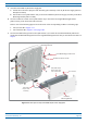
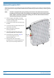
5 Assemblethe240WAC/DCPowerSupplyKit.
a AttachtheLocalPowerJumperCableAssembly(PN7774061)totheAC/DCPowerSupplyJunction
Box(PN
7774356).
b Usethefourscrews(PN100907-126)toattachthe240WAC/DCPowerSupplyassemblytotheWall
MountingBracket(PN
7771350).
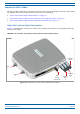
6 UsethesixM6-1.0x14mmscrews(PN100901-50)toattachthetwoAngledMountingBrackets
(PN
7771351)tothebackoftheCAPLchassis.
RefertooneofthefollowingfiguresforthelocationofthecorrespondingsixM6-1.0mountingtaps:
• CAPL,noFanKit—Figure7-11
• CAPLwithFanKit—Figure7-12onpage108.
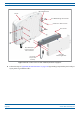
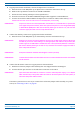
7 UsethefourM8x16flange-headscrews(PN100762-1)toattachtheassembled240WAC/DCPower
SupplyKitandWallMountingBrackettotheAngledMountingBracketsthatyouattachedtotheCAP
Lin
Step6.
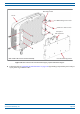
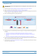
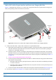
Figure 7-11. CAP L (No Fan Kit) with 240W AC/DC Power Supply Kit
Two Angled
Mounng Brackets
Four M8x16 flange-head screws
Six M6-1.0 x 14mm screws
Four screws
One Wall
Mounng Bracket
48V, 240W AC/DC
Power Supply Unit
with Juncon Box
Local Power
Jumper Cable
Assembly