
User's Manual Part 2


ION
®
-E Series Hardware Installation Guide M0201AA
Page 104 © June 2017 CommScope, Inc.
Installing CAP Ls
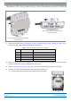
5 AttachtheHybridFiberSpliceBox(PN7693816-00)totheWallMountingBracket(PN7771350).[Use
what screws? None were shown in the assembly drawings. Or does it clip to the bracket?
]
6 UsethesixM6-1.0x14mmscrews(PN100901-50)toattachthetwoAngledMountingBrackets
(PN
7771351)tothebackoftheCAPLchassis.
RefertooneofthefollowingfiguresforthelocationofthecorrespondingsixM6-1.0mountingtaps:
• CAPL,noFanKit—Figure7-8
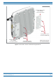
• CAPLwithFanKit—Figure7-9onpage105.
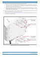
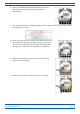
7 UsethefourM8x16flange-headscrews(PN100762-1)toattachtheassembledHybridFiberSpliceBox
andWallMountingBrackettotheAngledMountingBracketsthatyouattachedtotheCAP
LinStep6.
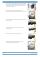
Figure 7-8. CAP L (No Fan Kit) with Power Supply / Hybrid Fiber Mounting Kit
Six M6-1.0 x 14mm screws
One Hybrid
Fiber Splice Box
One Wall Mounng Bracket
Two Angled
Mounng Brackets
Four M8x16 flange-head screws
NOTE: Install a CAP L that does not
have a Fan Kit vercally.