
User's Manual Part 2


M0201AA ION
®
-E Series Hardware Installation Guide
© June 2017 CommScope, Inc. Page 79
Identifying CAP Ls in the ION-E Software
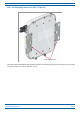
CAP L with an Optical Fiber Interface
Connectors
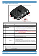
REF # Label Description Function
1, 4 ANT 3, ANT 4 Not available; connector is plugged.
2ANT 1
4.3-10 RF connector
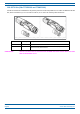
RF connectors that connect to two separate external antennas or to two ports on a
cross-polarized dual antenna via 50Ω coaxial cable. Each connector supports two RF
bands as described in Table 7-2 on page 77. The end of the 50Ω coaxial cable that
connects to an ANT connector can be either a push-pull or a threaded connector. If not
used, an ANT connector must be plugged.
3ANT 2
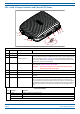
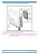
6 Unlabeled Pushbutton switch Turns power to CAP L on/off. Power to the CAP L may also be shutdown via the ION-E
Series Software. [verify can power off via GUI]
CAUTION! Prior to disconnecting the Power cable from the CAP L, press the Power
button to power off the CAP L.
7 Unlabeled 36 to 60 Vdc Power
connector
Proprietary 4-pin connector that connects to a local or remote DC power supply, or to a
Hybrid Fiber Junction Box.
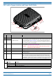
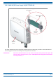
8 2 Optical Port 2 Optical Port 2 connects to an optional cascaded CAP L unit and provides the main signal
interface. Optical transport occurs over Single Mode Fiber (SMF) or Multi Mode Fiber
(MMF). This port must be plugged if not in use.
9 1 Optical Port 1 Optical Port 1 connects to an ION-E CAN/TEN (possibly through a local Hybrid Fiber
Junction Box) and provides the main signal interface. Optical transport occurs over Single
Mode Fiber (SMF) or Multi Mode Fiber (MMF); the appropriate SFP+ is factory-installed
according to order specifications.
10 A Auxiliary port The AUX port provides a connection for external Ethernet devices such as WiFi and IP
cameras. Cabling is via the appropriate CAT cable for the protocol; this model supports an
1000 BASE-T and 802.3at Class 3 Power over Cat6A Ethernet connection. Maximum
attached cable length is 3 meters (9.8 feet). The AUX port must be plugged if not in use.
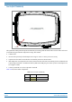
Power LED (unlabeled)
Ref # LED Color Description
5 • Blue • CAP L is powered on and operational.
• Flashing blue • CAP L is powered on and initializing.
• Off • CAP L is not powered on.
For further information, see "Powering a CAP L” on page 82.
1
2
3
4
7
8
9
10
5
6