
User's Manual Part 1


M0201AA ION
®
-E Series Hardware Installation Guide
© June 2017 CommScope, Inc. Page 51
UAPs and UAP-N25s
TheUAPandUAP-N25transmitandreceivesignalsviaCat6AcablingbetweentheCAN/TENandanindoor
antenna.TheUAPalsosupportsEthernetbackhauloranadditionalUAPthroughasecondRJ45jack.
TheUAP-N25issimilartotheUAP.UAPssupport380to2700MHzinfour75-MHzblocks.TheN25hasafilter
thatrestrictsthesecondreceiverto25MHz.ThisallowsION-Etosupportcertainbandcombinationsin
whichanarrowreceivebandexistsbetweentwotransmitbands.
The UAP and UAP-N25 are designed for indoor use only.
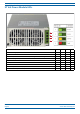
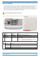
UAP Connectors
Ref # Component Device Function
1 Main port RJ45 connector Provides data and power to UAP over Cat6A.
2 AUX port RJ45 connector Provides data and power to 2nd UAP or Ethernet devices.
3 Power button Pushbutton switch Turns power to UAP on/off. Power to the UAP may also be shutdown via the
ION-E Series Software.
CAUTION! Prior to disconnecting a Cat6A cable from the UAP, press the
red Power button to power off the UAP.
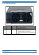
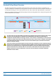
UAP Status LED (unlabeled)
Ref # LED Color Description
4 • Blue • UAP is transmitting as expected.
• Fast-flash blue • Unit Identifier activated in the ION-E GUI; for information on how to flash identify a UAP, see “Flash UAP
Led” section of the ION-E Series software configuration guide that corresponds to the ION-E Software
Release installed on this ION-E system.
• Slow-flash blue • UAP firmware update is in process.
• Yellow • Active alarm; see Active Alarms page in GUI.
Front of UAP
4
Boom of UAP (paral view)
1
2
3