
Installation Guide
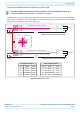
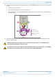
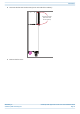
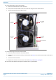
Table Of Contents
- Table of Contents
- Document Overview
- ERA System Overview
- CAP H Overview
- Safely Working with a CAP H
- Installing a CAP H
- Using the Status LED to Determine State of the CAP H
- Maintenance
- Contacting CommScope

CommScope ERA
®
High Power Carrier Access Point Installation Guide M0201AKG_uc
Page 56 © February 2021 CommScope, Inc.
Maintenance
6 Do the following to remove the Fan Unit:
a Unscrew and disconnect the fan connector.
b Unscrew the four Pan-head screws that secure the fan plate to the CAP H chassis.
c Pull the Fan Unit from the CAP H chassis.
7 Do the following to install the new Fan Unit:
a Insert the new Fan Unit into the CAP H chassis.
b Use the four Pan-head screws that you removed in step Step 6 to secure the new Fan Unit to the CAP H
chassis.
c Connect the fan connector.
d Replace the Fan Unit cover that was removed in Step 4 and Step 5 on page 55.
8 Reconnect the CAP H to mains power and make sure it is powered on.
Fan connector
Pan-Head
screw
Pan-Head
screw
Pan-Head
screw
Pan-Head
screw