
Installation Guide
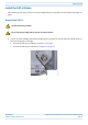
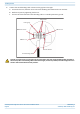
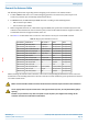
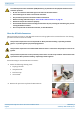
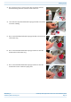
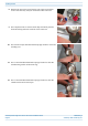
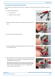
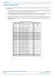
Table Of Contents
- Table of Contents
- Document Overview
- ERA System Overview
- CAP H Overview
- Safely Working with a CAP H
- Installing a CAP H
- Using the Status LED to Determine State of the CAP H
- Maintenance
- Contacting CommScope

M0201AKG_uc CommScope ERA
®
High Power Carrier Access Point Installation Guide
© February 2021 CommScope, Inc. Page 45
Installing a CAP H
2 Connect the CAP H Optical Port 1 as appropriate for this installation. Note the maximum range listed in
Table 12. See "CAP H Connectors and Status LED" on page 6 for the location of Optical Port 1.
a Remove the dust cap from the CAP H Optical Port 1 connector and the connectors on the SMF or MMF.
b Follow the local cleaning technique to clean Optical Port 1.
c Clean the connectors on the SMF or MMF following the fiber supplier’s recommendations.
d Install the SFP+ connector and Optical OCTIS Kit on the end of the SMF or MMF that will connect to
the CAP H, and then connect that end of the fiber to the CAP H Optical Port 1 connector. (Refer to the
technical data sheet that ships with the OCTIS Kit for further information.)
e Connect the other end of the SMF or MMF to an open port on the OPT Card.
3 Do the following only if cascading a Secondary CAP H, connect Optical Port 2 of the Primary CAP H to
Optical Port 1 of the Secondary CAP H. (Cascading of CAP H APs requires SW V2.7 or higher.)
a Raise the lever on the EMI/IP67 cap on Optical Port 2 connector and remove the cap.
b Remove the caps from the connectors on the SMF or MMF.
c Follow the local cleaning technique to clean Optical Port 2.
d Clean the connectors on the SMF or MMF following the fiber supplier’s recommendations.
e Install an SFP+ and Optical OCTIS Kit on the end of the fiber that will connect to the Primary CAP H
and connect that end of the SMF or MMF to the CAP H Optical Port 2 connector.
• Note the maximum range listed in Table 12. See "CAP H Connectors and Status LED" on page 6 for the
location of Optical Port 2.
• Refer to the technical data sheet that ships with the OCTIS Kit for further information.
f Install an SFP+ and Optical OCTIS Kit on the end of the fiber that will connect to the Secondary CAP H
and connect that end of the SMF or MMF to the CAP H Optical Port 1 connector on the cascaded
Secondary CAP H.
Connect an Auxiliary Device
Port A (Auxiliary port) will provide a connection for external Ethernet devices such as WiFi and IP cameras.
(The Auxiliary port is not supported in the current software version.)
Do the following to connect an auxiliary device.
1 Raise the lever on the EMI/IP67 cap on Port A and remove the cap (for the location of Port A, see
"CAP H Connectors and Status LED" on page 6).
2 Install the Ethernet OCTIS Kit on the end of the cable that will connect to the CAP H, and then connect that
end of the cable to CAP H Port A. (Refer to the technical data sheet that ships with the OCTIS Kit for further
information.)
3 Connect the other end of the CAT cable to the Ethernet port of the auxiliary device.
Port A must be plugged if not in use.
This cable cannot exceed 3 meters (9.8 feet).