
Installation Guide
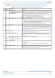
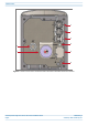
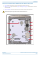
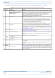
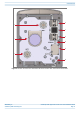
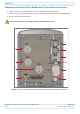
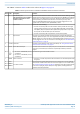
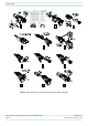
Table Of Contents
- Table of Contents
- Document Overview
- ERA System Overview
- CAP H Overview
- Safely Working with a CAP H
- Installing a CAP H
- Using the Status LED to Determine State of the CAP H
- Maintenance
- Contacting CommScope

M0201AKG_uc CommScope ERA
®
High Power Carrier Access Point Installation Guide
© February 2021 CommScope, Inc. Page 9
CAP H Overview
Connectors and Status LED on Models with Two Antenna Connectors
• Figure 4 shows the connectors on an AC version with two antenna connectors.
• Table 3 on page 10 maps the callouts in Figure 4 and Figure 5 on page 11 and describes the connectors
and STATUS LED.
• Figure 5 on page 11 shows the connectors on a DC version with two antenna connectors.
Figure 4. Location of Connectors and Status LED on AC Version with Two Antenna Connectors
Do not remove caps from any of the connectors until instructed to do so.
1
2
3
4
6
7
5
9
8