
Installation Guide
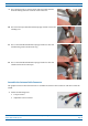
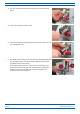
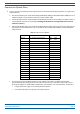
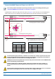
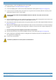
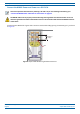
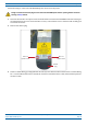
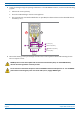
Table Of Contents
- Table of Contents
- Document Overview
- Era System Overview
- CAP H Overview
- Safely Working with a CAP H
- Installing a CAP H
- Using the Status LED to Determine State of the CAP H
- Maintenance
- Contacting CommScope

CommScope Era
™
High Power Carrier Access Point Installation Guide M0201AKC
Page 40 © April 2019 CommScope, Inc.
Installing a CAP H
2 Connect the CAP H Optical Port 1 as appropriate for this installation. Note the maximum range listed in
Table 10. See "CAP H Connectors and Status L
ED" on page 6 for the location of Optical Port 1.
a R
emove the dust cap from the CAP H Optical Port 1 connector and the connectors on the SMF or MMF.
b F
ollow the local cleaning technique to clean Optical Port 1.
c C
lean the connectors on the SMF or MMF following the fiber supplier’s recommendations.
d Install the SFP+ connecto
r and Optical OCTIS Kit on the end of the SMF or MMF that will connect to
the CAP H, and then connect that end of the fiber to the CAP H Optical Port 1 connector. (Refer to the
tech
nical data sheet that ships with the OCTIS Kit for further information.)
e C
onnect the other end of the SMF or MMF to an open port on the OPT Card.
3 D
o the following only if cascading a Secondary CAP H, connect Optical Port 2 of the Primary CAP H to
Optical Port 1 of the Secondary CAP H. (CascadingofCAPHAP
sisnotsupportedinthecurrent
softwareversion.)
a Rai
se the lever on the EMI/IP67 cap on Optical Port 2 connector and remove the cap.
b Rem
ove the caps from the connectors on the SMF or MMF.
c F
ollow the local cleaning technique to clean Optical Port 2.
d C
lean the connectors on the SMF or MMF following the fiber supplier’s recommendations.
e I
nstall an SFP+ and Optical OCTIS Kit on the end of the fiber that will connect to the Primary CAP H
and connect that end of the SMF or MMF to the CAP H Optical Port 2 connector.
• N
ote the maximum range listed in Table 10. See "CAP H Connectors and Status LED" on page 6 for the
location of Optical Port 2.
• Re
fer to the technical data sheet that ships with the OCTIS Kit for further information.
f I
nstall an SFP+ and Optical OCTIS Kit on the end of the fiber that will connect to the Secondary CAP H
and connect that end of the SMF or MMF to the CAP H Optical Port 1 connector on the cascaded
Secondary CAP H.
(Optional) Connect an Auxiliary Device
Port A (Auxiliary port) provides a connection for external Ethernet devices such as WiFi and IP cameras. (The
AuxiliaryportandexternalEthernetdevicesarenotsupportedinthecurrentsoftwareversion.)
If appropriate for this installation, do the following to connect an auxiliary device.
Port A must be plugged if not in use.
1 Ra
ise the lever on the EMI/IP67 cap on Port A and remove the cap (for the location of Port A, see
"CAP H Connectors and Status LED" on page 6).
2 I
nstall the Ethernet OCTIS Kit on the end of the cable that will connect to the CAP H, and then connect that
end of the cable to CAP H Port A. (Refer to the technical data sheet that ships with the O
CTIS Kit for further
information.)
This cable cannot exceed 3 meters (9.8 feet).
3 C
onnect the other end of the CAT cable to the Ethernet port of the auxiliary device.