
Installation Guide
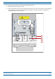
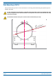
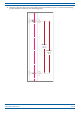
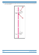
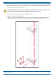
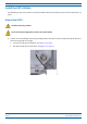
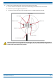
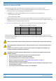
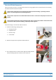
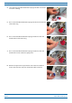
Table Of Contents
- Table of Contents
- Document Overview
- Era System Overview
- CAP H Overview
- Safely Working with a CAP H
- Installing a CAP H
- Using the Status LED to Determine State of the CAP H
- Maintenance
- Contacting CommScope

CommScope Era
™
High Power Carrier Access Point Installation Guide M0201AKC
Page 34 © April 2019 CommScope, Inc.
Installing a CAP H
Connect the Antenna Cable
The following information regarding antenna mapping and is relevant to all CAP H variants.
• F
or Non-MIMO bands, there is no channel mapping option for the transceiver/antenna port. The
transceiver/antenna port relationship is fixed in hardware.
• F
or MIMO bands, the Era GUI maps MIMO channels according to their AP designation:
– A
P0 to antenna port ANT1
– A
P1 to antenna port ANT2.
• When using SISO channels on a CAP H that supports MIMO, the system will automatically balance t
he
number of channels between the two antenna ports, where the first SISO channel is mapped to ANT1, the
second SISO channel is mapped to ANT2, and so on.
• Use Table 9 to determine how to connect to t
he antenna correctly for each CAP H variation.
Table 9. Mapping CAP H Models to Antennas
Part Number Model Name ANT or ANT 1 ANT 2
7772983-xxxx CAP H 8/9/18/21 8/9/18/21 Not Applicable
7821740-xxxx CAP H 9/18/21/26 9/18/21/26 Not Applicable
7825719-xxxx CAP H 7E/80-85/17E/19 7E/80-85/17E/19 Not Applicable
7825730-xxxx CAP H 17E/17E/19/19 17E/19 (MAIN) 17E/19 (MIMO)
When attaching the antenna cable connector, refer to the corresponding documentation of the connector
manufacturer. The bending radius of the antenna cable must remain within the given specifications. Observe
all cautions listed below.
Make sure that the fiber cable used meets the RF and environmental requirements for this installation.
Use an appropriate torque wrench for the 4.3-10 type connectors (5 N-m, 44 in lb) with 22mm (7/8) in
opening.
Do NOT use your hands or any other tool (such as a pair of pliers). This might cause damage to the
connector and lead to a malfunction of the CAP H.
To minimize passive inter-modulation (PIM) distortion, pay attention to the physical condition of the
connector junctions:
• Do not use connectors that show
signs of corrosion on the metal surface.
• Prevent the ingress of water or dirt into the connector.
• Use protective caps for the connectors when not mounted.
• Before mounting follow the steps in "Clean the RF Cable Connectors" on page 35.
• Attach and torque the connectors properly.
• Avoid metallic abrasion when mounting
the connectors by only screwing the connecting nut, but not
turning the whole connector.
• Use a torque wrench to fasten th
e connector, as described above.