
Installation Guide
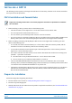
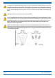
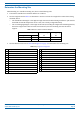
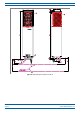
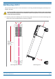
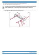
Table Of Contents
- Table of Contents
- Document Overview
- Era System Overview
- CAP H Overview
- Safely Working with a CAP H
- Installing a CAP H
- Using the Status LED to Determine State of the CAP H
- Maintenance
- Contacting CommScope

M0201AKC CommScope Era
™
High Power Carrier Access Point Installation Guide — Preliminary
© April 2019 CommScope, Inc. Page 25
Installing a CAP H
Wall Mounting a CAP H
This procedure tells you how to mount the CAP H to a wall using the Wall Mounting Kit (CommScope Part
Number 7661581).
It is the responsibility of the installer to verify that the supporting surface will safely support the combined
load of the electronic equipment and all attached hardware and components and to ensure that the CAP H
is
safely and securely mounted.
1 M
ark the position of the drilling holes. The following graphic shows the location of the mounting holes
and the pitch of the CAP H during the mounting procedure.
135mm
(5.31”)
Minimum:
775 mm (30.51”)
Maximum
788 mm (31”)
Mounng Hole Locaons Mounng Pitch